
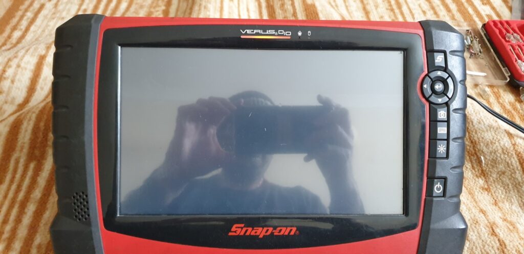
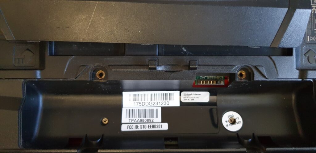
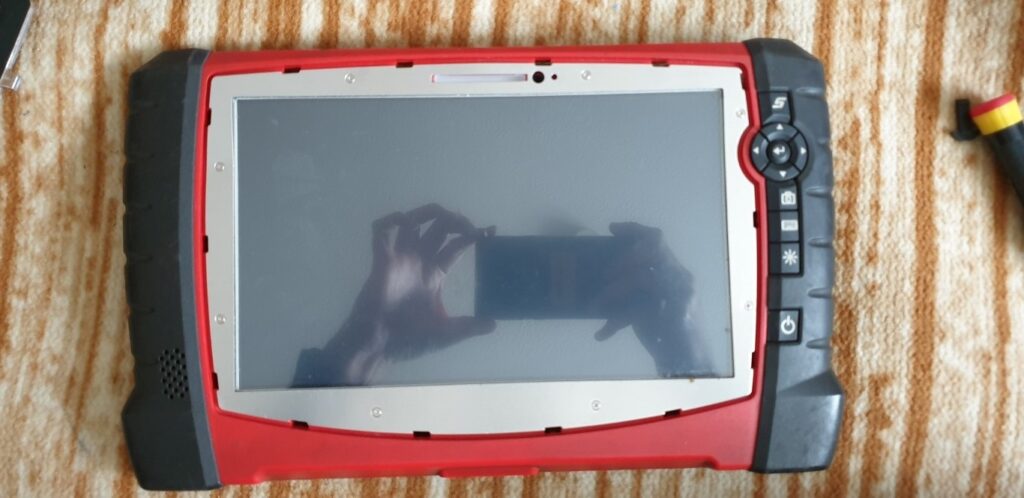
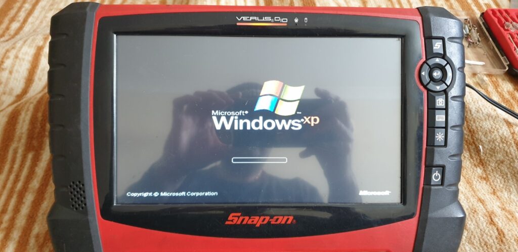
Once again, my mechanic friend needed help as his Snap-on diagnostic reader (Snap-on Verus Pro EEHD301-6) had its screen totally blank/dead. Upon pressing the power button, the machine did appear to turn-on because I was able to see the power led turn on however there was nothing on the screen, like so:
So, I looked for this issue on internet but could not find anything substantial, no idea why! After searching a lot, I did come across a blog post reply where someone had mentioned that this may be due to the RAM inside the diagnostic machine. Still no concrete information like this article. I almost discarded the idea of RAM issue becasue the symptom was that the display was blank/dead which normally means issue with the display.
Also, due to regular wear and tear, the charger female input socket on the motherboard had become loose and was not making battery charging connection very reliably.
Then I thought, in the absence of any other leads, let me try on the couple of leads that I do have: replacing RAM and replacing or re-soldering the power connector. The tools required are a multi-bit screwdriver and suitable RAM replacement part.
I had never opened a diagnostic machine before but I had seen it working at my friend’s garage before. You see, this machine is a portable computer with Windows XP Embedded OS. Therefore, it is bound to have all the essential components of a computer such as RAM, Screen/display, Hard drive and a motherboard with a processor.
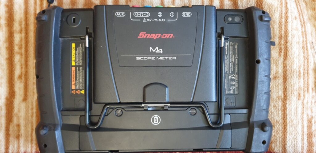
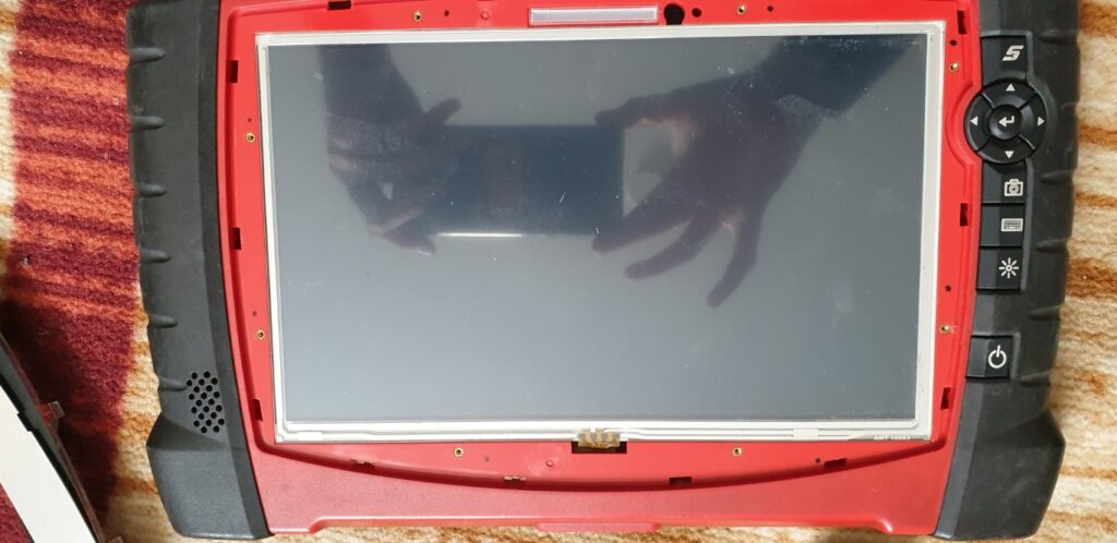
So I started disassembling the diagnostic machine, like so:
I can’t remember removing the front panel was actually required. I originally thought of replacing the screen so I started with removing the front panel. You may not need to remove the front panel as the RAM is deep inside the back side of the unit. I do not think you need to remove the front panel.
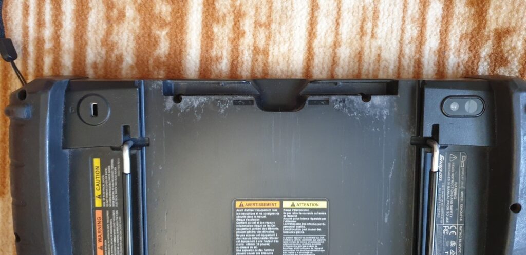
Going to back side, detaching the back cover.
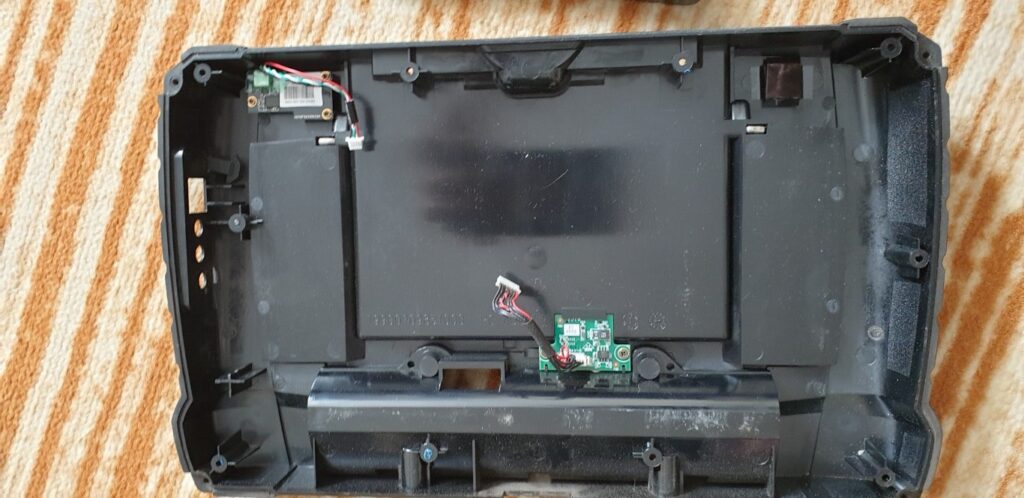
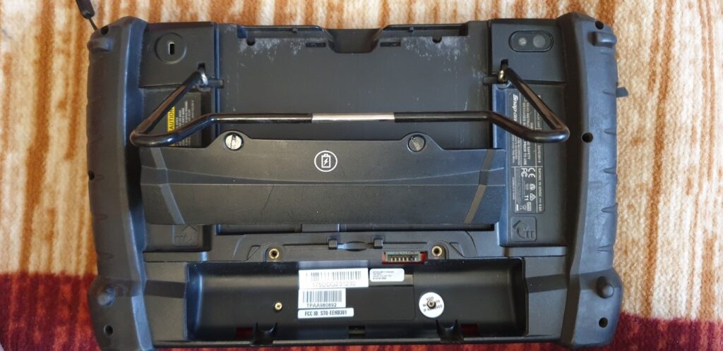
The following image is what I saw when I opened the back cover. What I realised that there was no RAM to be seen on this side of the board which meant the RAM must have been beneath the motherboard. This meant opening the whole board and reaching behind it to replace the RAM.
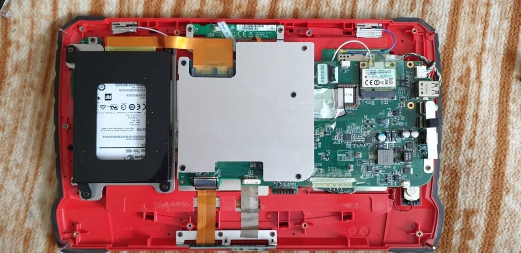
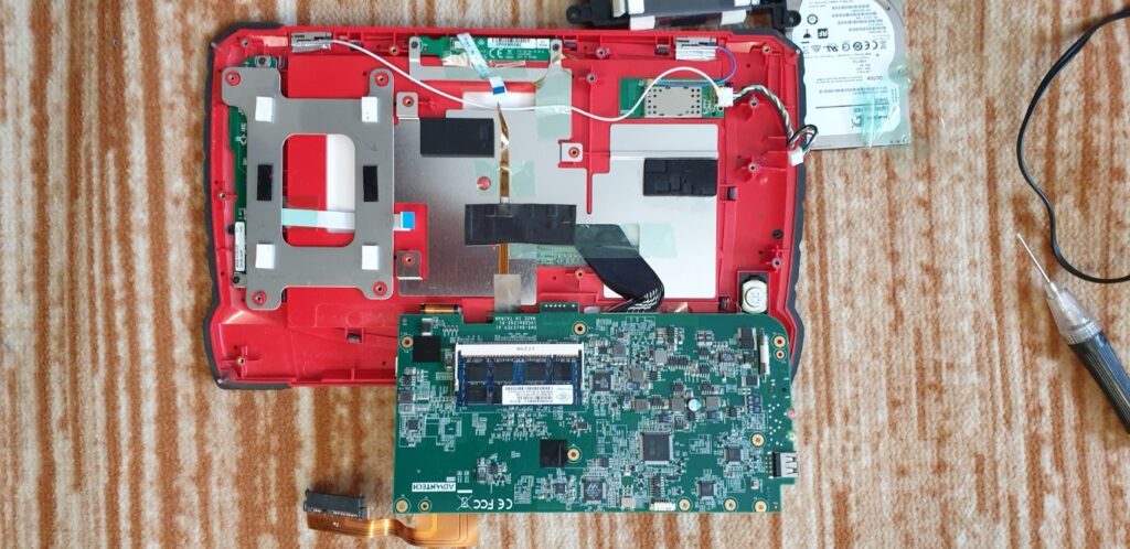
So I had to disassemble the top plate which served as a heatsink for the processor. I removed the hard drive, just in case. The hard drive is enclosed in the black frame in the above photo.
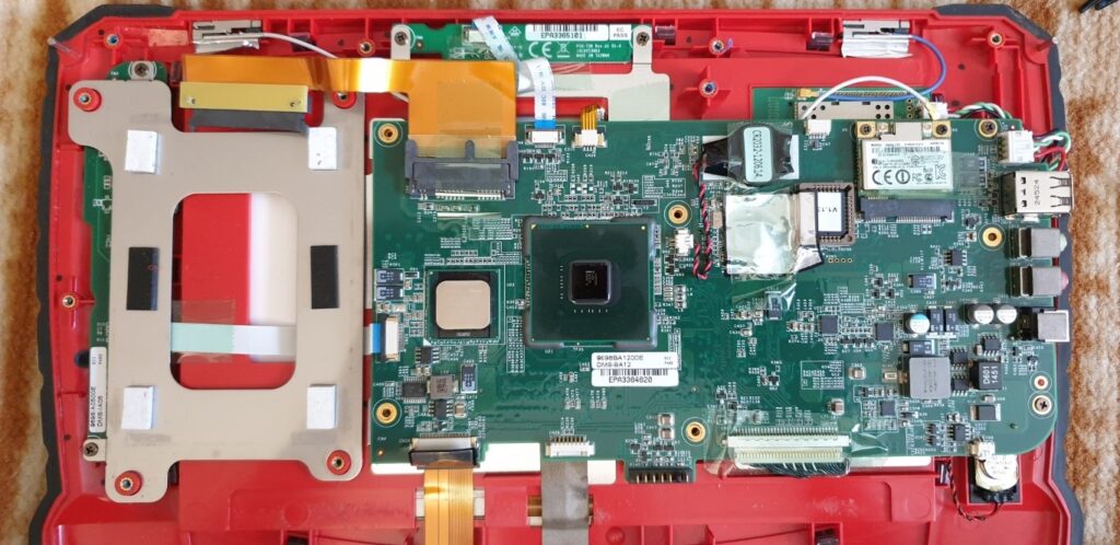
The processor is visible once I removed the heat-sink Aluminum plate.
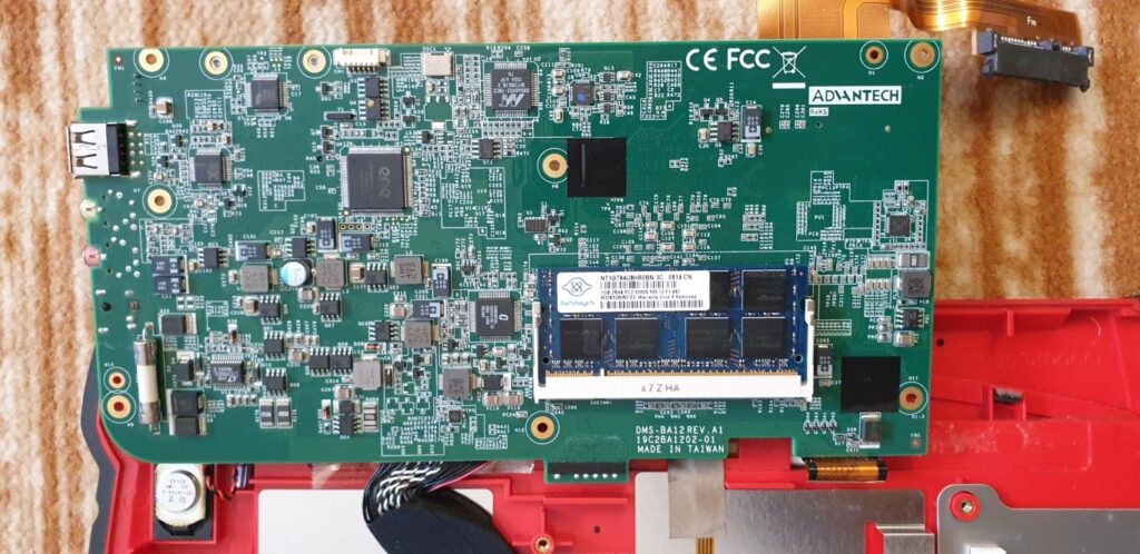
So now you see the RAM SODIMM socket. It is on the back side of the motherboard. Very hard to reach. So I then replaced the RAM with a suitable good one.
At this point, I was still not confident whether this was going to work. Then I re-soldered the power connector to make sure it is not moving about and loose due to the wear and tear of pushing in and out the charger pin.
I then re-assembled the entire unit in the reverse order and then powered-on the unit. Guess what, the unit came to life :).
Quite a good learning for me as I would not have doubted RAM for a dead/blank display.
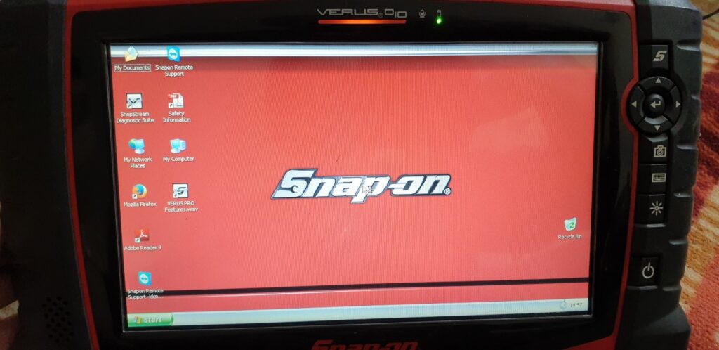
I then fully charged the battery and got the unit fully functioning.
