Gear stick of older Pajeros with Automatic Transmission get stuck in certain position and will not budge, will not move. This is because of the flimsy plastic gear stick shift sleeve which is underneath the gear knob is broken as shown in the video.
This plastic sleeve looks like the following and is quite cheap to buy a new one. The replacement process is shown in the video below and is very easy to do it yourself.
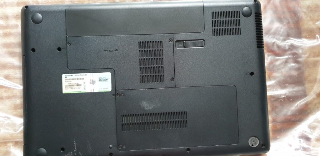
I have an HP G62 SA laptop with Core-i3 330M which I purchased in 2010. Recently, it started powering off after using for a few minutes. I suspected heat-sink compound issue. Either the heat-sink compound has dried-up and as a result not letting the heat-sink make a contact with the processor surface. So I decided to open it up and investigate, like so:
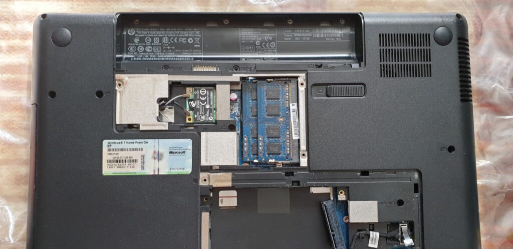
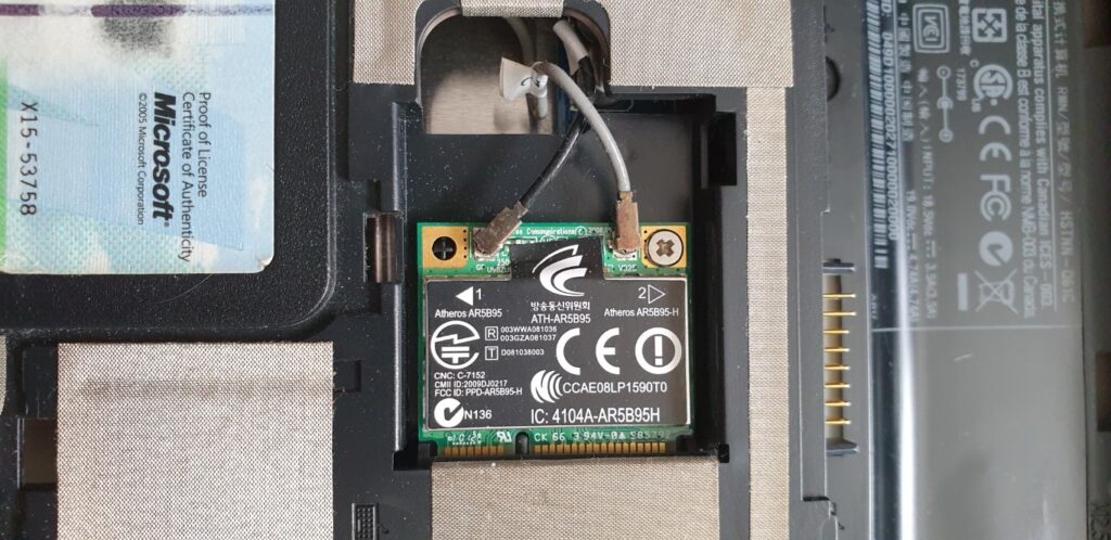
Now disconnect the Wifi module:
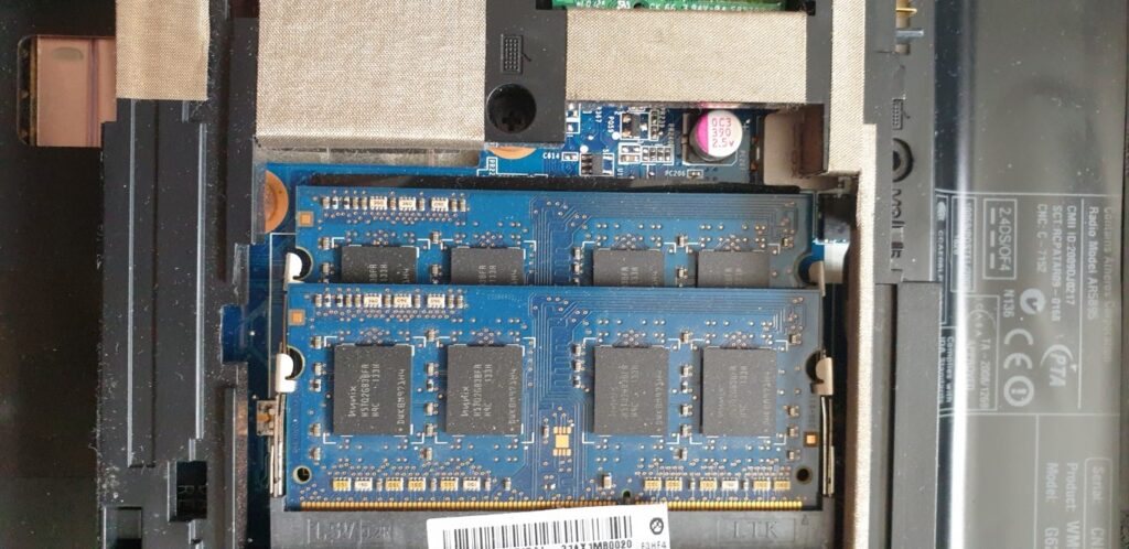
Remove the RAM modules:
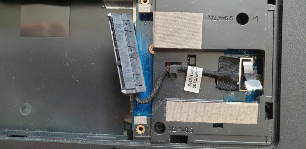
Remove the hard drive:
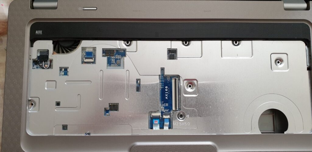
Coming to the front side, removing the keyboard. There are screws underneath the keyboard that hold mother board and the back plate in place. So have to explose the front side and unscrew those screws.
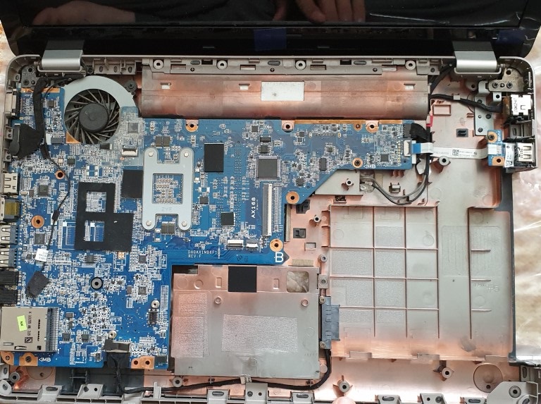
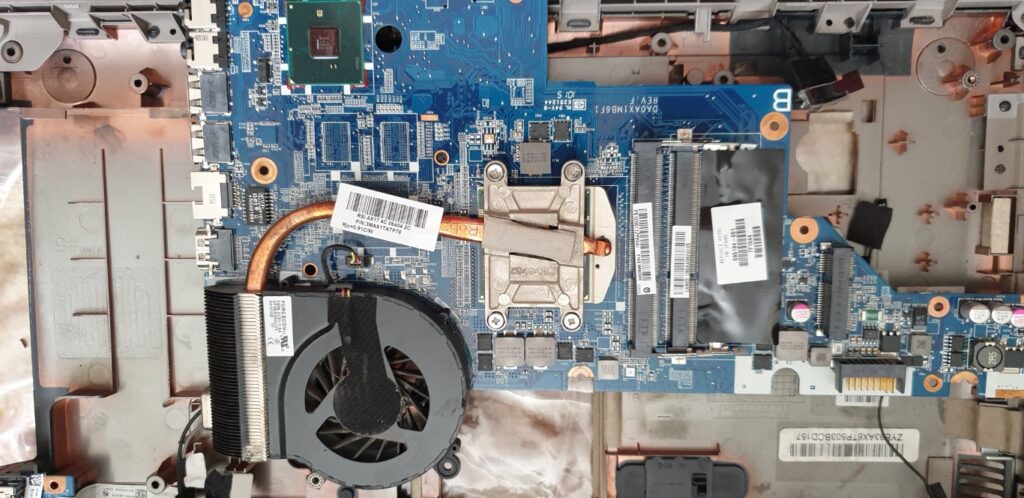
The heatsink is not on the top side of the motherboard so need to go behind:
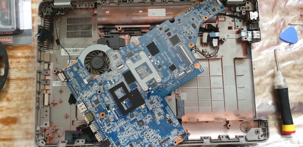
As you can see, the fan is connected with the heatsink through the copper tubing. The processor is underneath the heatsink.
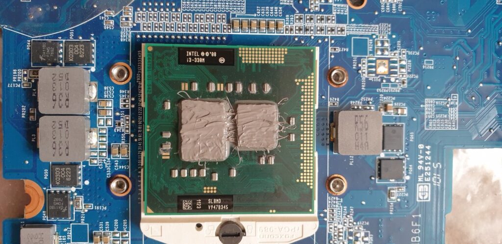
Upon removing the heat-sink, I found out that the heat-sink gel had indeed dried and as a result there was less contact between the two surfaces and hence much less heat conduction.
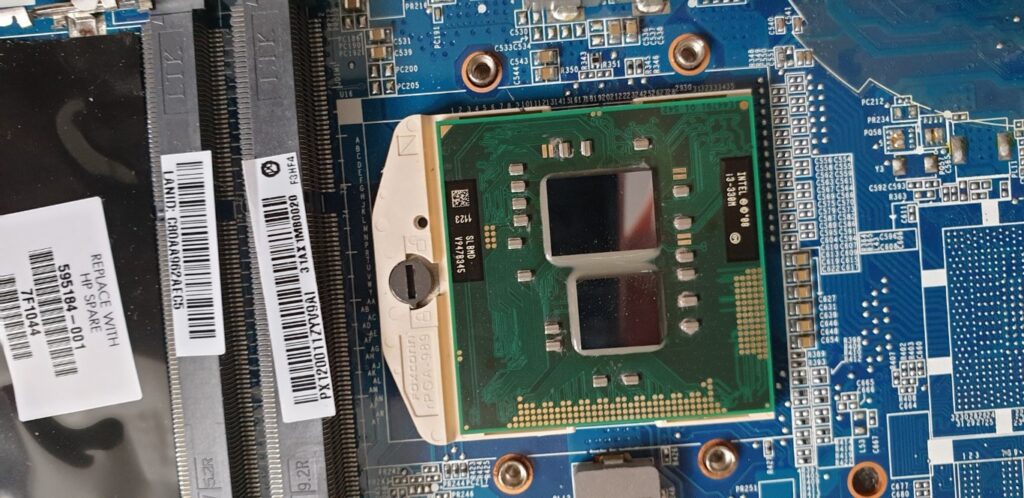
Cleaned the surface of the processor:
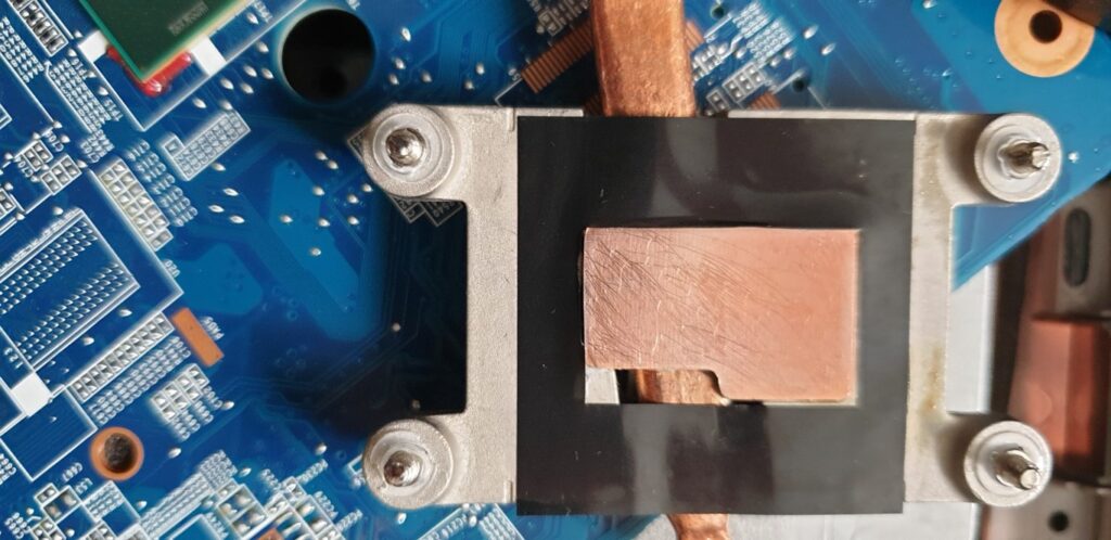
Clean the bottom of the heat-sink:
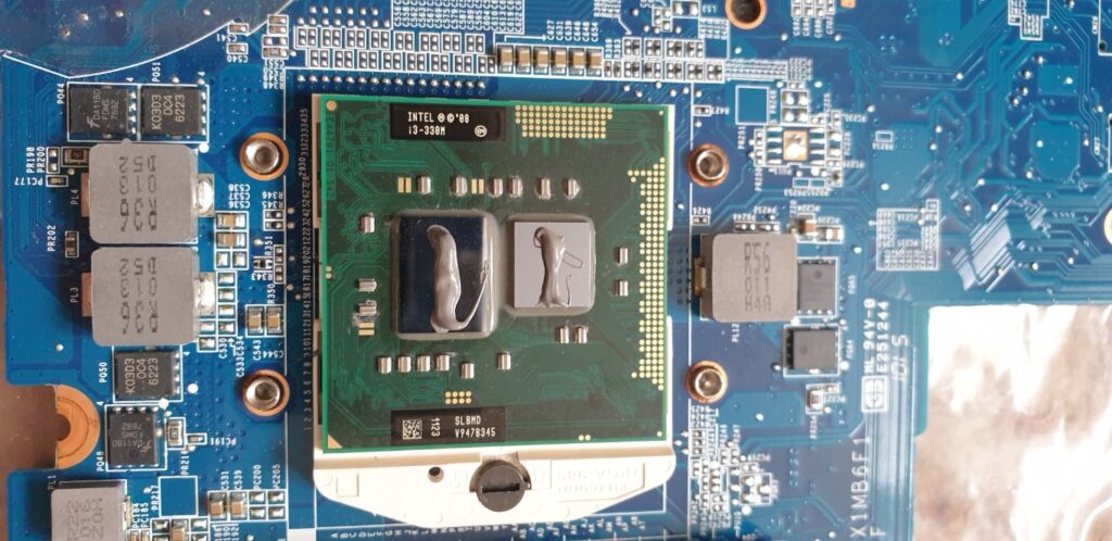
Now, applying new heat-sink compound or gel. There are many articles explaining how to apply the gel such as in a straight line, in a cross etc. I went for the straight line and then spread-it method:
Also, make sure you do not over tighten the heatsink screws, they need to be as tight as it can go. This is because, otherwise, it will sequeeze out the heat-sink gel and the heat conduction will be affected.
After replacing the heat-sink compound, I put back the entire laptop in reverse order and started the laptop. Guess what, it no longer cuts off :).
Probably added another 5-10 years of life in the laptop as I managed to get a free upgrade to the OS from Windows 7 to Windows 10. I also upgarded the RAM and hard drive.
I have been using a Grundig Vivance LCD TV since 2008 and it had recently developed a fault that had a symptom of screen flickering continuously. I have had no issues with this TV for more than 10 years so it had worked quite reliably and as a result I was unable to make the expenditure to buy a new one.
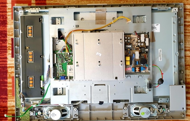
So just when I thought, finally time to buy a new one, my curiousity got the better of me :). I decided to investigate and wanted to look inside. Generally, a TV screen flicker is attributed to power supply capacitor(s) issue. I then opened up the TV, like so:
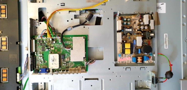
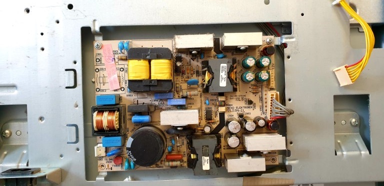
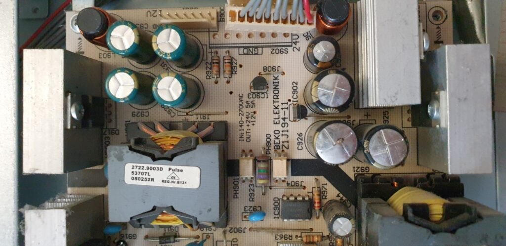
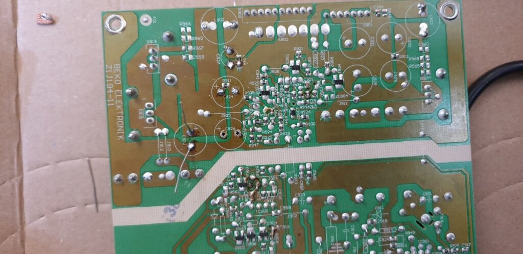
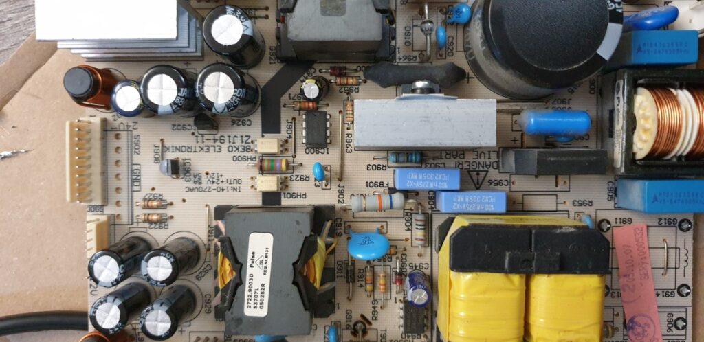
The power supply board/section is easy to spot because it starts where the electrical inlet power plug is inserted. Please make sure you have disconnected the power supply :), an obvious precaution. In this TV, the power supply section is a separate board which is shown on the right hand side in the above image. I then opened up the Faraday metal cage around the power supply board and show zoomed-in photos as follows:
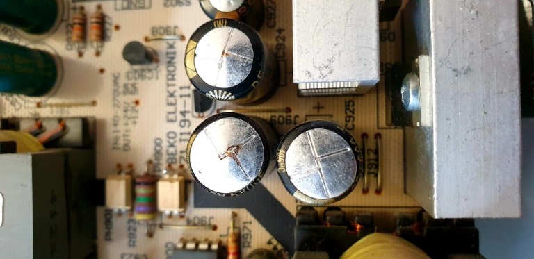
I then further zoom in to see how the capacitors were doing:
Did you spot what I was suspecting? Have a look in the photo below, one of the capacitors has become a bit bloated and also leaked something out.
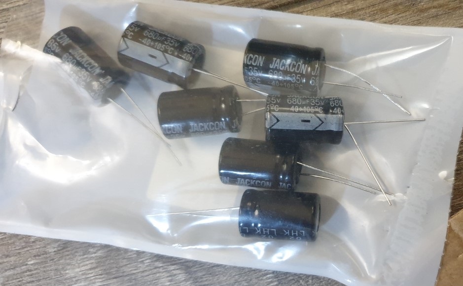
That is the issue. Therefore, I decided the replace all the capacitors of the power supply board. I ordered it from Farnell UK and it arrived at my home in a bag like the following:
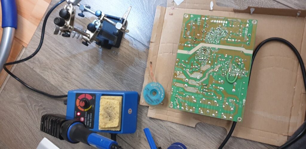
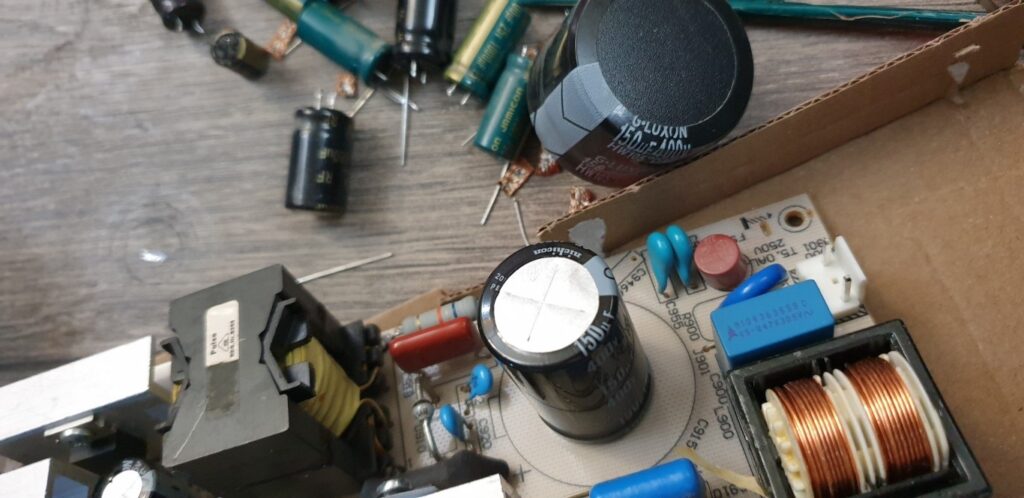
So I started de-soldering the old ones and replacing them with new ones:
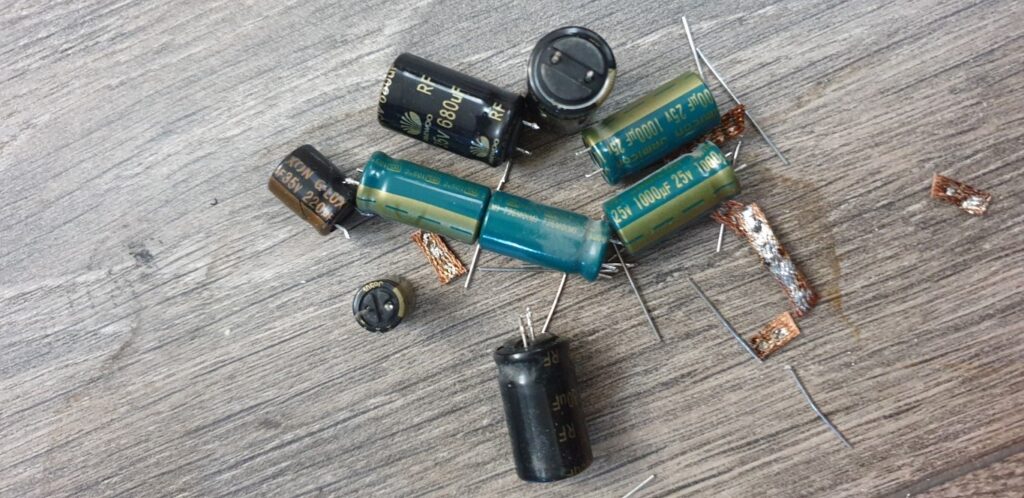
Here are the old de-soldered capacitors:
Now you see the new capacitors on the top side of the board:
So after replacing all the capacitors on the board, I put everything together and started the TV. Guess what, the TV had no flicker what so ever. I probably extended the TV’s life for another 10 years at a cost of £25 for the capacitors :).
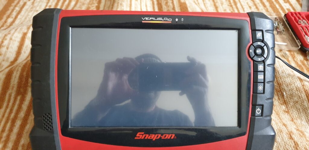
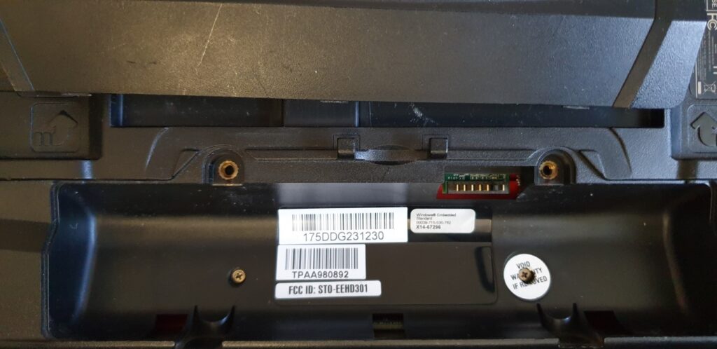
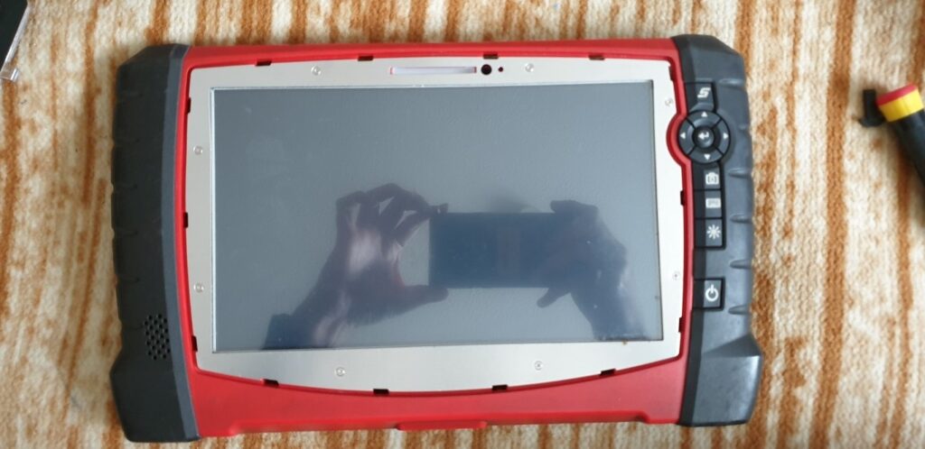
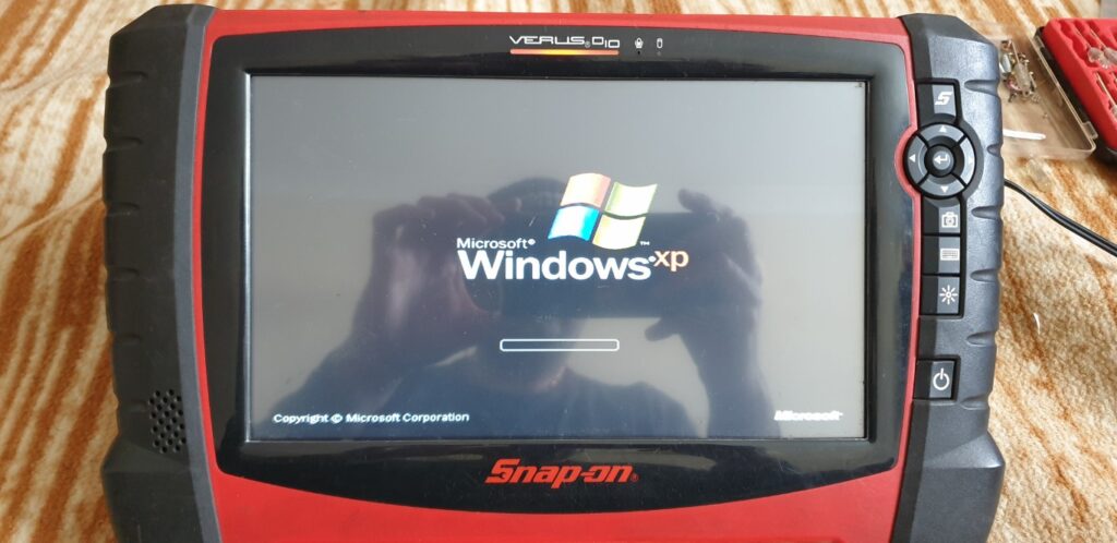
Once again, my mechanic friend needed help as his Snap-on diagnostic reader (Snap-on Verus Pro EEHD301-6) had its screen totally blank/dead. Upon pressing the power button, the machine did appear to turn-on because I was able to see the power led turn on however there was nothing on the screen, like so:
So, I looked for this issue on internet but could not find anything substantial, no idea why! After searching a lot, I did come across a blog post reply where someone had mentioned that this may be due to the RAM inside the diagnostic machine. Still no concrete information like this article. I almost discarded the idea of RAM issue becasue the symptom was that the display was blank/dead which normally means issue with the display.
Also, due to regular wear and tear, the charger female input socket on the motherboard had become loose and was not making battery charging connection very reliably.
Then I thought, in the absence of any other leads, let me try on the couple of leads that I do have: replacing RAM and replacing or re-soldering the power connector. The tools required are a multi-bit screwdriver and suitable RAM replacement part.
I had never opened a diagnostic machine before but I had seen it working at my friend’s garage before. You see, this machine is a portable computer with Windows XP Embedded OS. Therefore, it is bound to have all the essential components of a computer such as RAM, Screen/display, Hard drive and a motherboard with a processor.
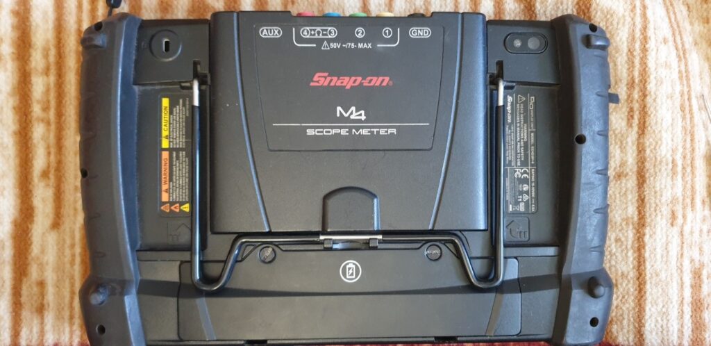
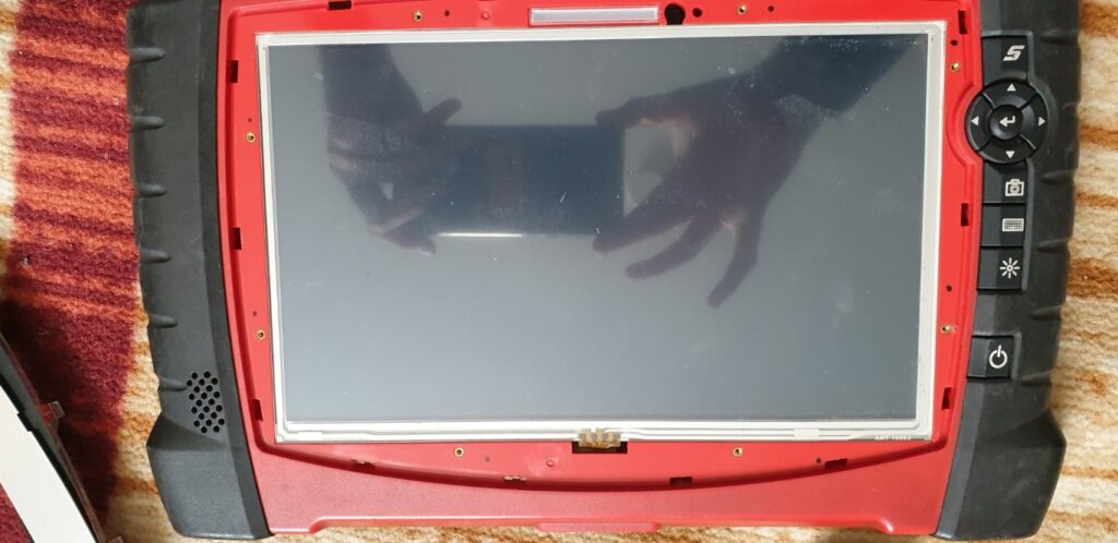
So I started disassembling the diagnostic machine, like so:
I can’t remember removing the front panel was actually required. I originally thought of replacing the screen so I started with removing the front panel. You may not need to remove the front panel as the RAM is deep inside the back side of the unit. I do not think you need to remove the front panel.
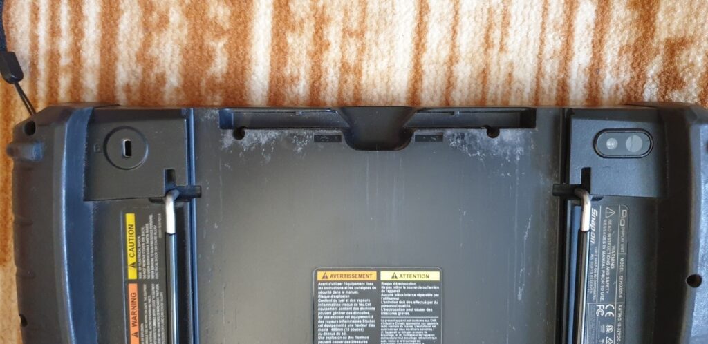
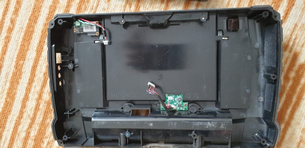
Going to back side, detaching the back cover.
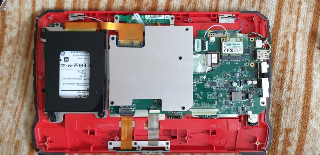
The following image is what I saw when I opened the back cover. What I realised that there was no RAM to be seen on this side of the board which meant the RAM must have been beneath the motherboard. This meant opening the whole board and reaching behind it to replace the RAM.
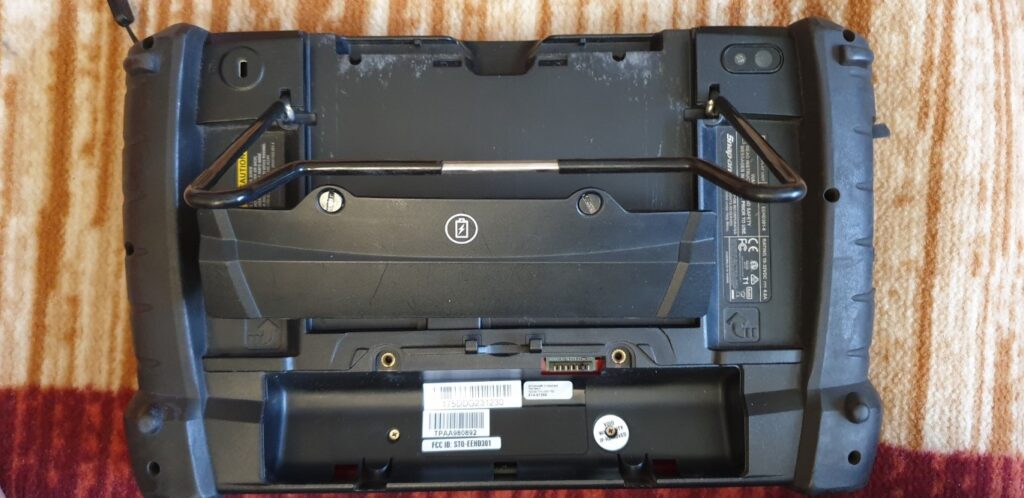
So I had to disassemble the top plate which served as a heatsink for the processor. I removed the hard drive, just in case. The hard drive is enclosed in the black frame in the above photo.
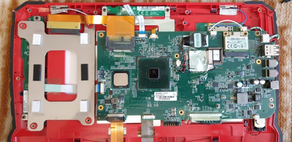
The processor is visible once I removed the heat-sink Aluminum plate.
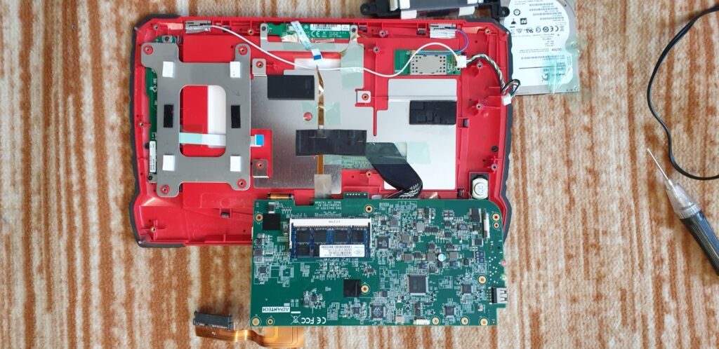
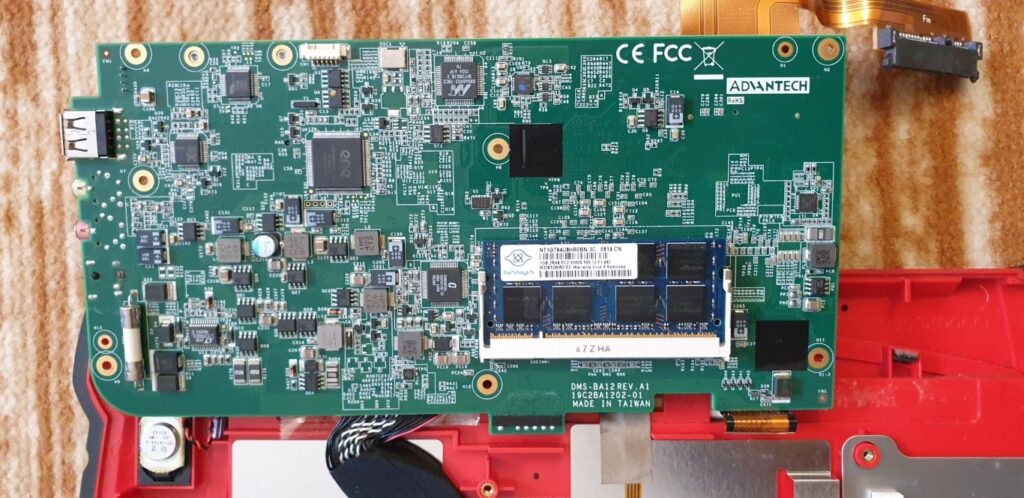
So now you see the RAM SODIMM socket. It is on the back side of the motherboard. Very hard to reach. So I then replaced the RAM with a suitable good one.
At this point, I was still not confident whether this was going to work. Then I re-soldered the power connector to make sure it is not moving about and loose due to the wear and tear of pushing in and out the charger pin.
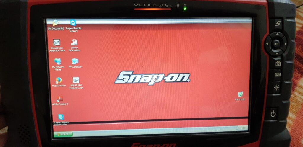
I then re-assembled the entire unit in the reverse order and then powered-on the unit. Guess what, the unit came to life :).
Quite a good learning for me as I would not have doubted RAM for a dead/blank display.
I then fully charged the battery and got the unit fully functioning.
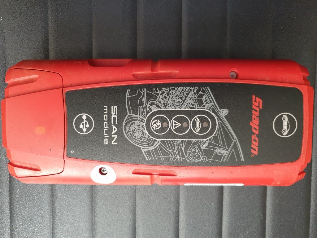
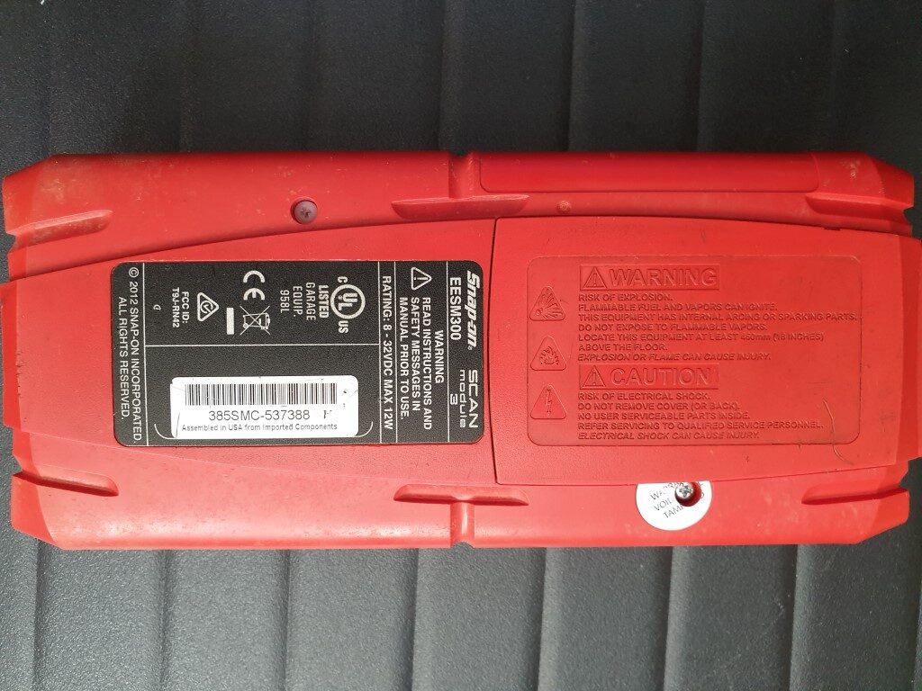
A mechanic friend accidentally dropped his SnapOn Bluetooth Scan Module. This caused the module to stop working.
The module looks like as shown in the following photos:
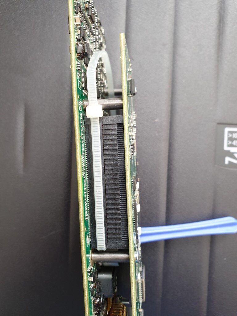
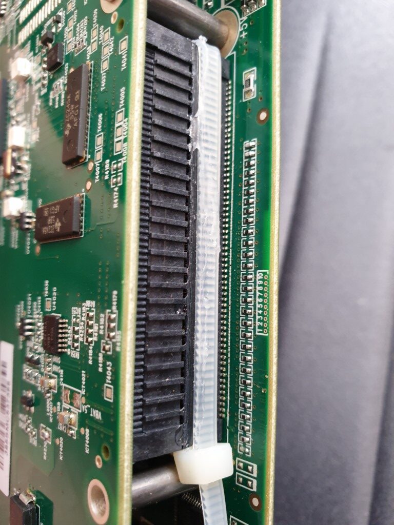
I then opened the scanner up. I noticed that there were two PCBs stacked on top of each other and connected by a big long multiple pin PCB connector, male part on one PCB and the female on the other.
Due to the fall, there was a crack in female connector. As a result of this, some of the pins on the male connector did not make connection to the famle ones and hence the scanner did not work.
The crack was very minor but because of it there was no strength that was holding, pushing the male connector pins against the female connector. So all it required was some sort of support for the cracked connector.
So rather than desoldering and replacing the entire connector which was a quite complex job, I thought, whatif I provided the support by some other means, it might just work.
So, I used a cable-tie and tied it around the cracked connector while putting some super glue to hold the cable-tie in place just in case :), like so:
I reconnected the two PCBs and reassembled the whole scanner and tested it.
Guess what, it worked! My mechanic friend is happily using it without any issues.
The main aim of this article is Repair, Reuse & Recyle.
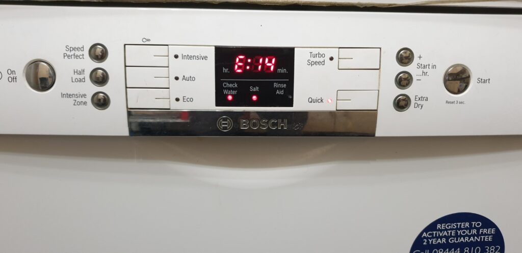
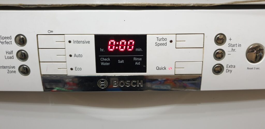
As per the Bosch website this error code means the following:
“An E14 error code indicates a flow meter failure or an issue with water flowing into the dishwasher or the filling system.”
First of all, check the inlet water supply to the dishwasher. Make sure there is no issue with inlet. The various checks that you can do are, check the dishwasher inlet tap/valve, check the plastic filters within the dishwasher inlet pipe etc.
If the error persits despite everything, it is very likely the flow meter issue. Please note, the following article details fix for Bosch dishwasher models that have the flow meter as depicted in this article however the fix is equally applicable to dishwasher models that have different looking flow meter components. The challenge on your part is to identify what the flow meter looks like in your dishwasher. Perhaps, searching on internet for the identification should help.
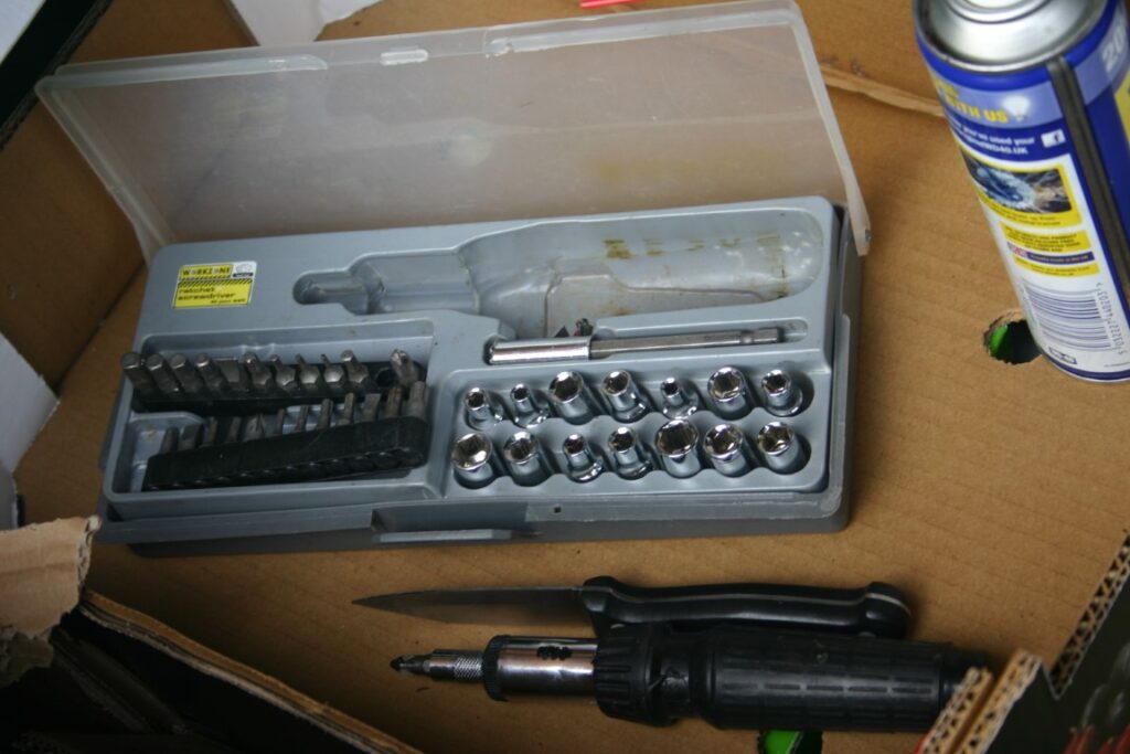
It is time to open the dishwasher. The tools required are very basic, such as multi-bit screwdriver set and the replacement part for the flow meter.
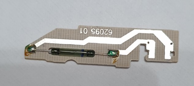
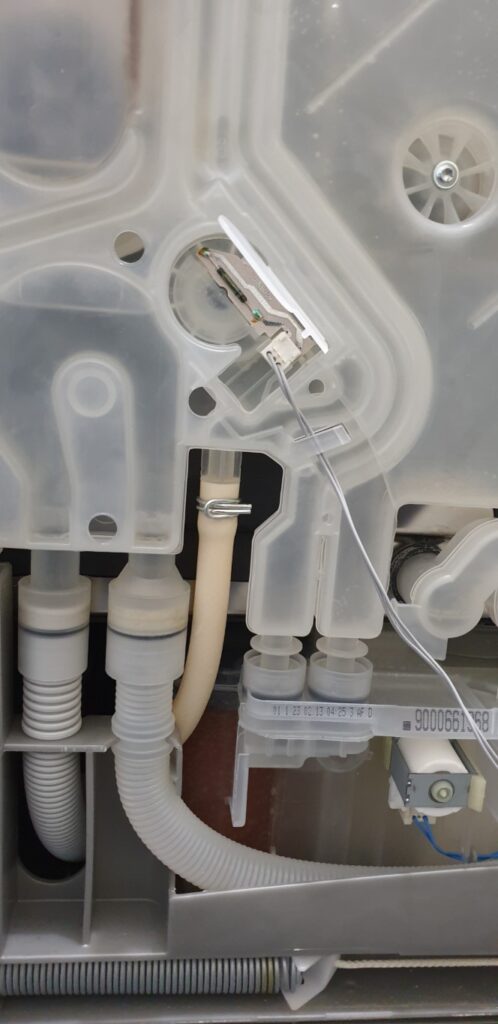
The flow meter in this Bosch dishwasher model looks like the following. This part only costs roughly £15-£25 when purchased online.
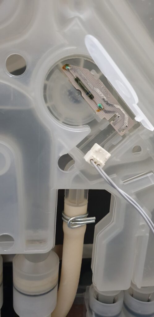
In fact, the sensor boad only has one electrical component and that is the tube looking part which is a Reed Relay. Just search online for to understand the function of a Reed relay. A Reed relay is nothing but a switch which made of two reeds which makes and breaks a contact if a magnet is passed in front. Over a number of years making and breaking the contacts, such relay can malfunction as it is an electro-mechanical component.
Such a Reed relay costs only 50p to £1 pound when purchased online. So, if you posses necessary skills to desolder the Reed relay on the old sensor board and source the exact part and solder it back to the board in the same manner as it was previously mounted, then you can solve this issue at an extremely cheap cost.
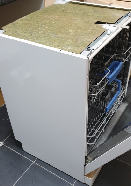
Therefore, the first thing to do is to disconnect the dishwasher from the power supply. Drag the dishwasher out of its cabinet. Then, first open up the top panel and then its side panels like so:
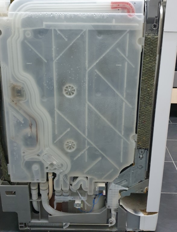
Now, let us locate the flow meter. The flow meter is housed underneath the white flap as shown in the following image:
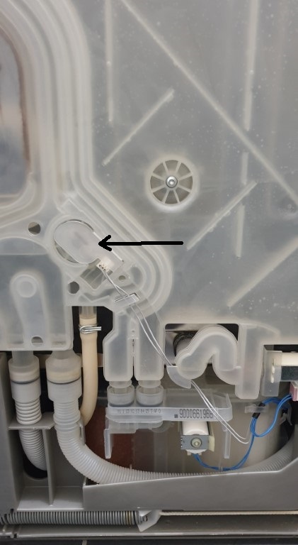
Next step is to carefully lift the plastic flap up so that the flow meter becomes visible:
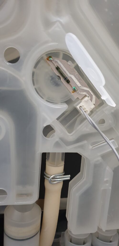
Then disconnect the connector that connects the grey cable to this flow meter, like so:
Now, carefully lift the flow meter and replace it with a new part and reconnect the cable like so:
Now, slowly and carefully push the plastic flap back into its position, just so that we do not break the flap:
Now, try running a wash cycle, the dishwasher should no longer display the error and finish its cycle normally:
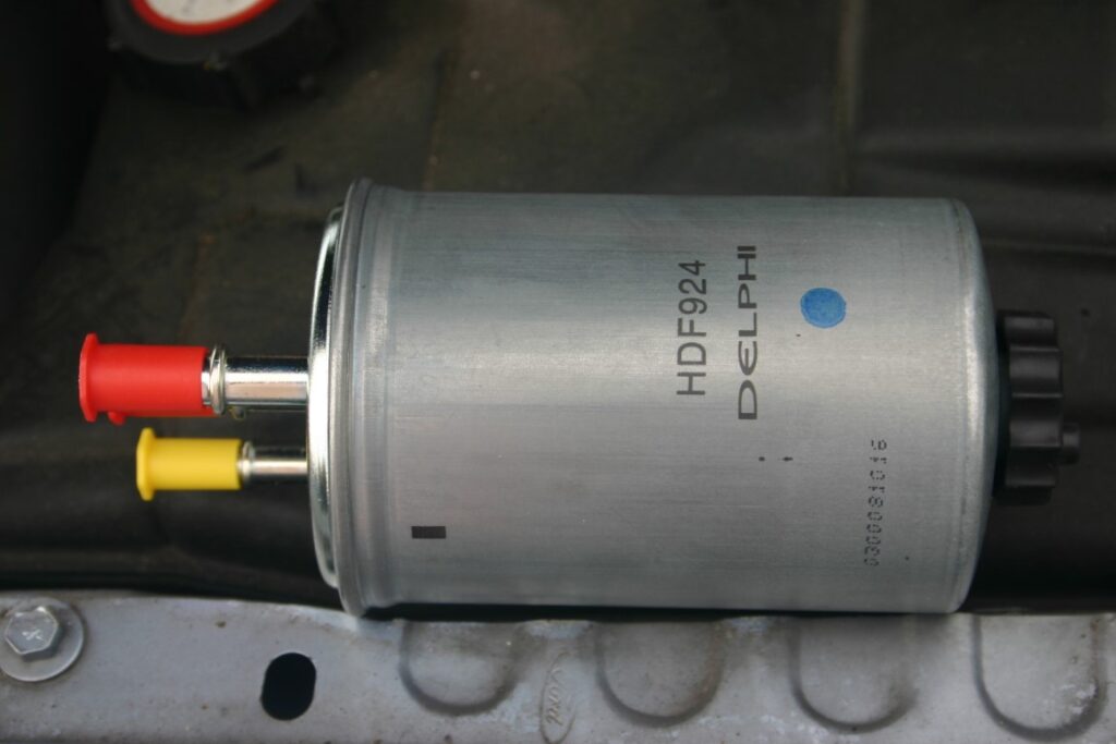
The particular car make and model that I will show how to change a fuel filter using detailed photographs is Ford Mondeo 2005, TDCI, 2 Litre Diesel, MK3. This demonstration is a part of an annual 10,000 miles full service of this car.
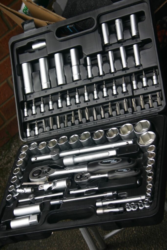
Tools required for this job: A small flat head screwdriver to unlock the fuel pipe plastic locks. A spanner set if you would like to remove the wheel spring mount incase you can’t reach/access the fuel filter easily.
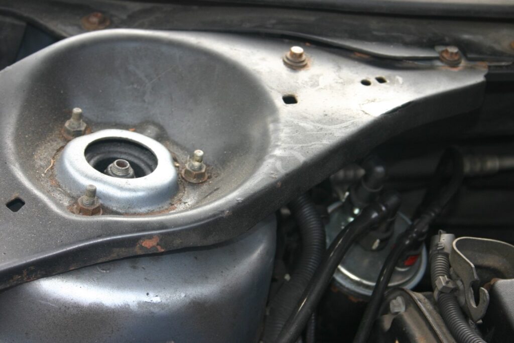
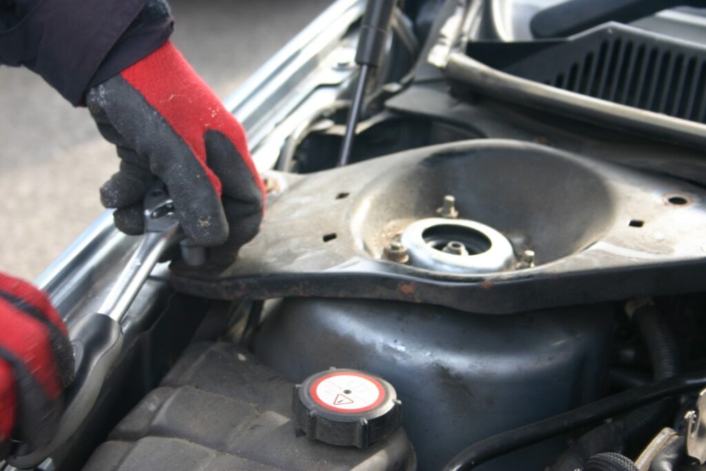
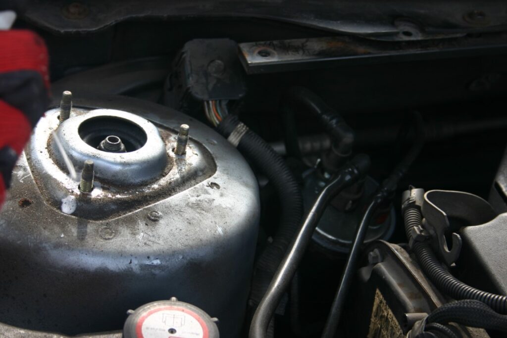
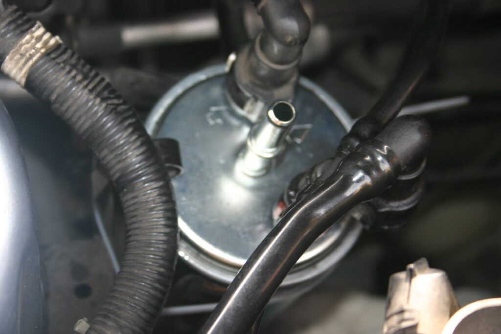
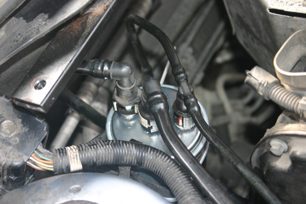
First thing is to locate the fuel filter in the engine bay. It is tucked underneath the wheel spring mount on the left side when facing the engine bay.
I decided to remove the wheel spring mount to gain easier access to the fuel filter however you can skip the following steps if you are comfortable reaching the 3 pipes connected to the filter.
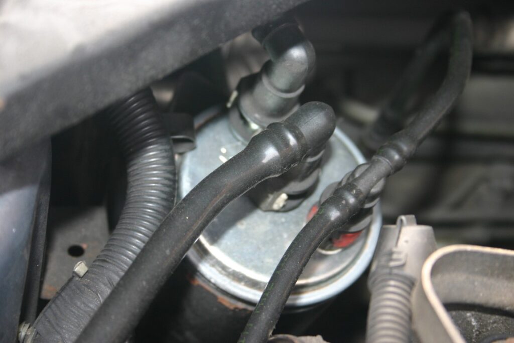
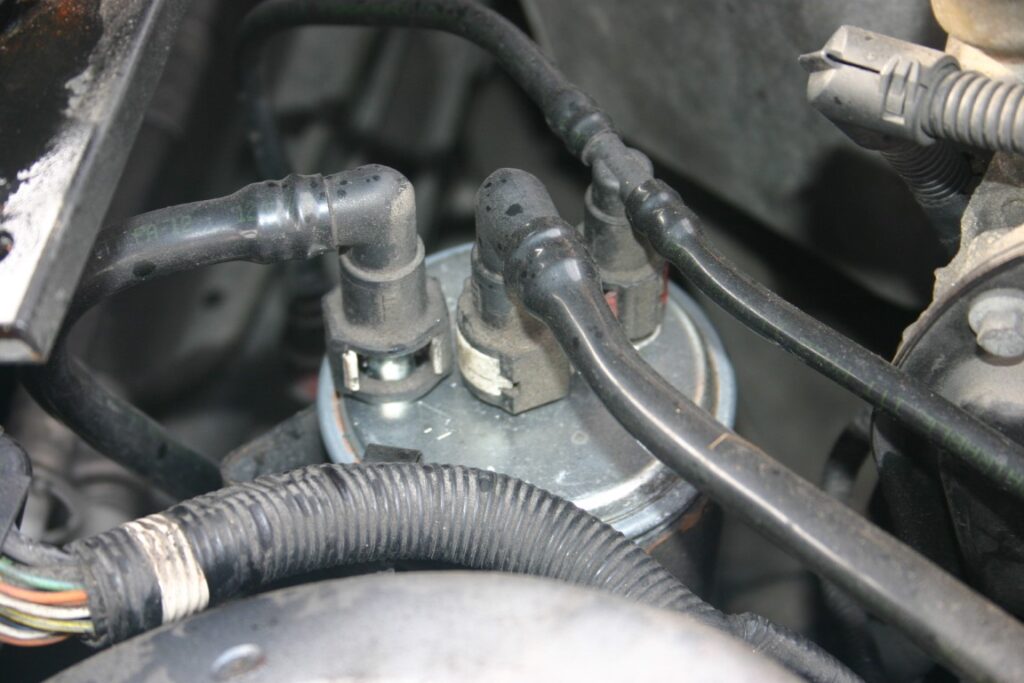
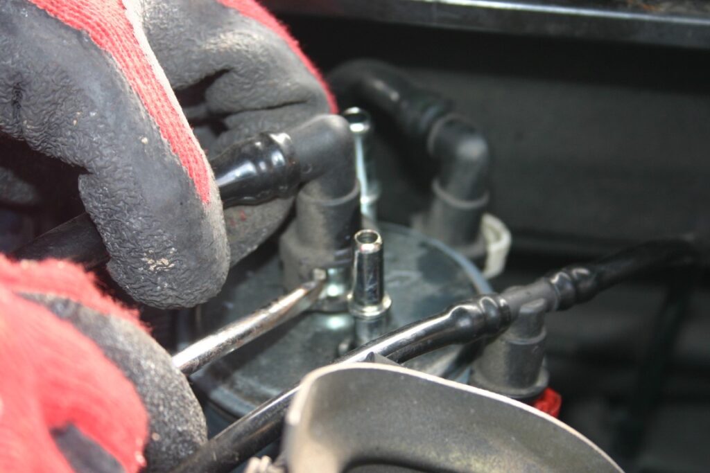
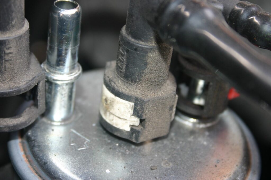
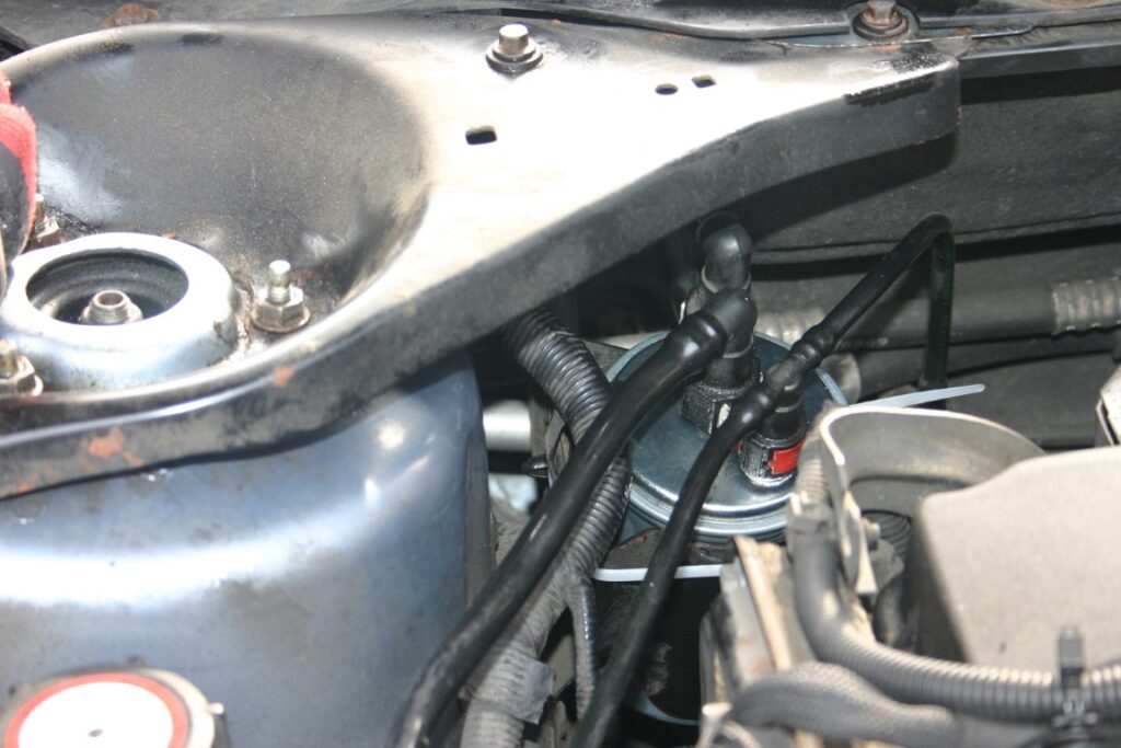
Using a small flathead screwdriver push the plastic locks of the fuel pipes connected to the fuel filter inlets and outlets as shown below:
Now replace the old fuel filter with a new one and connect the inlet fuel pipes and leave the outlet fuel pipe disconnected.
The new fuel filter MUST BE PRIMED WITH THE FUEL. If you do not prime the filter, it is impossible to start the car due to air lock in the filter and the fuel pipes. Therefore, you will need a fuel hand pump (squeezy rubber one, looks like the older blood pressure measurement device) which is used particularly to prime fuel filters.
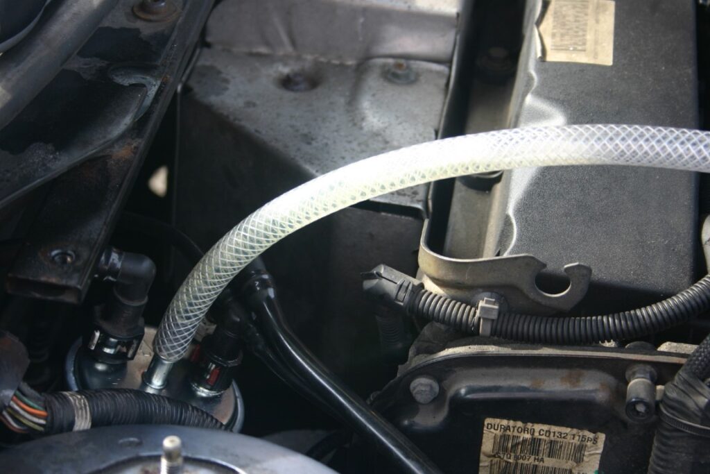
Alternatively, you will need a plastic pipe that snug fits the fuel filter outlet such that you can suck the air and hence bring the fuel through the filter like so:
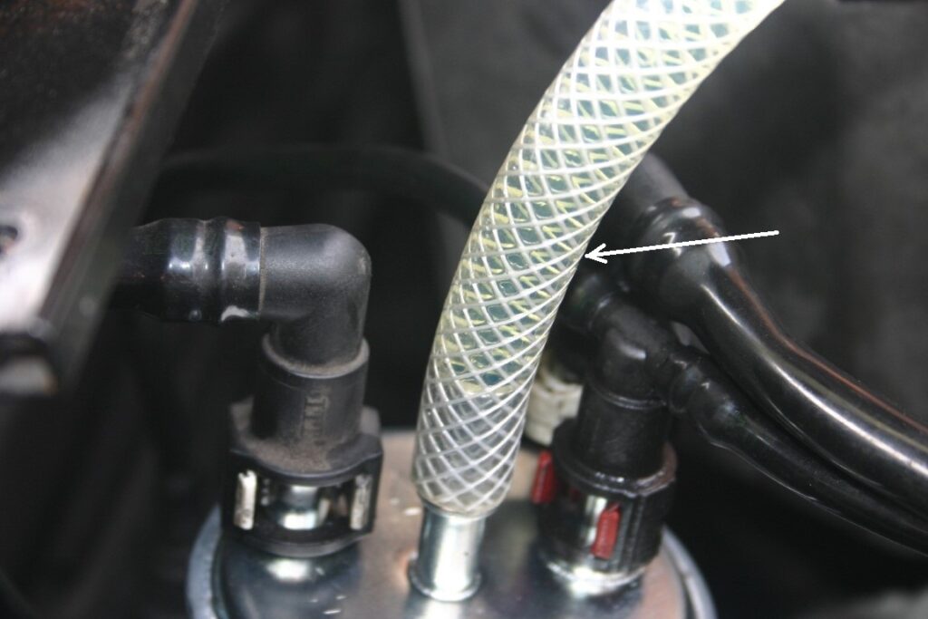
Please do not worry, as long as the pipe is long enough, the fuel will not end up in your mouth. All that is required is to bring the fuel just outside as visible in the pipe connected to the outlet of the filter, like so:
Once the fuel is visible from the filter outlet, disconnect the priming pipe and reconnect the black car’s fuel pipe. Now, when you start the car, the car should start in 2 or 3 shelf starts.
The particular car make and model that I will show how to change an air filter using detailed photographs is Ford Mondeo 2005, TDCI, 2 Litre Diesel, MK3. This is demonstration is a part of annual 10,000 miles full service.
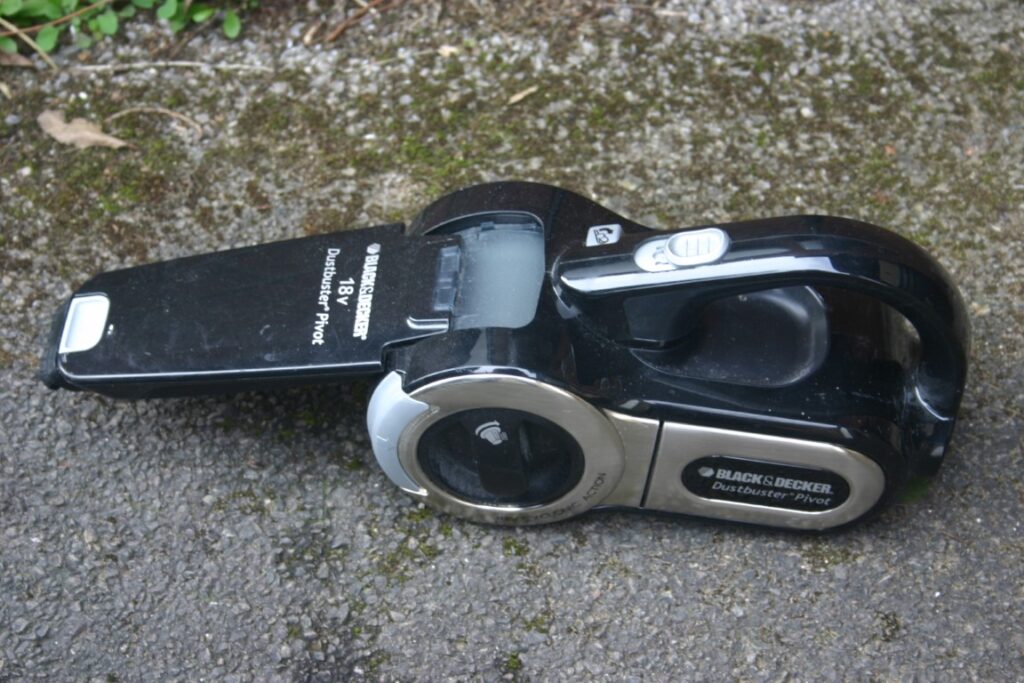
Tools required to replace an air filter: A replacement air filter, a multi-bit screwdiver and a vacuum cleaner.
A Screwdriver with different sized bits
A vacuum cleaner
A suitable new air filter
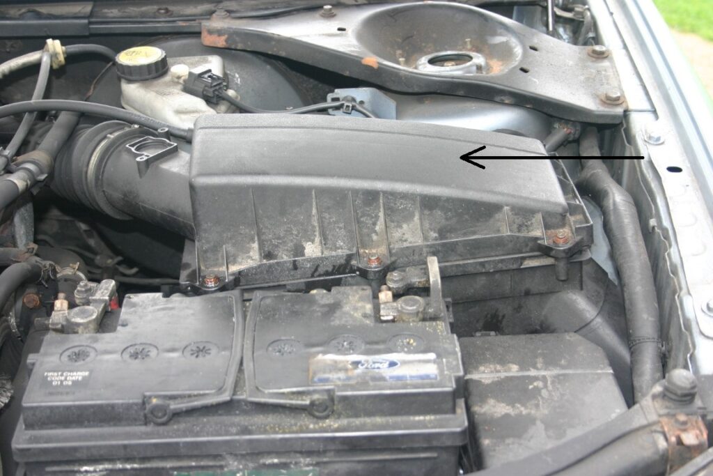
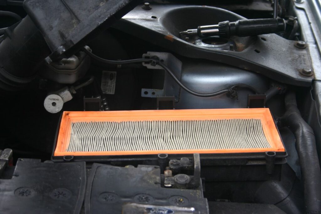
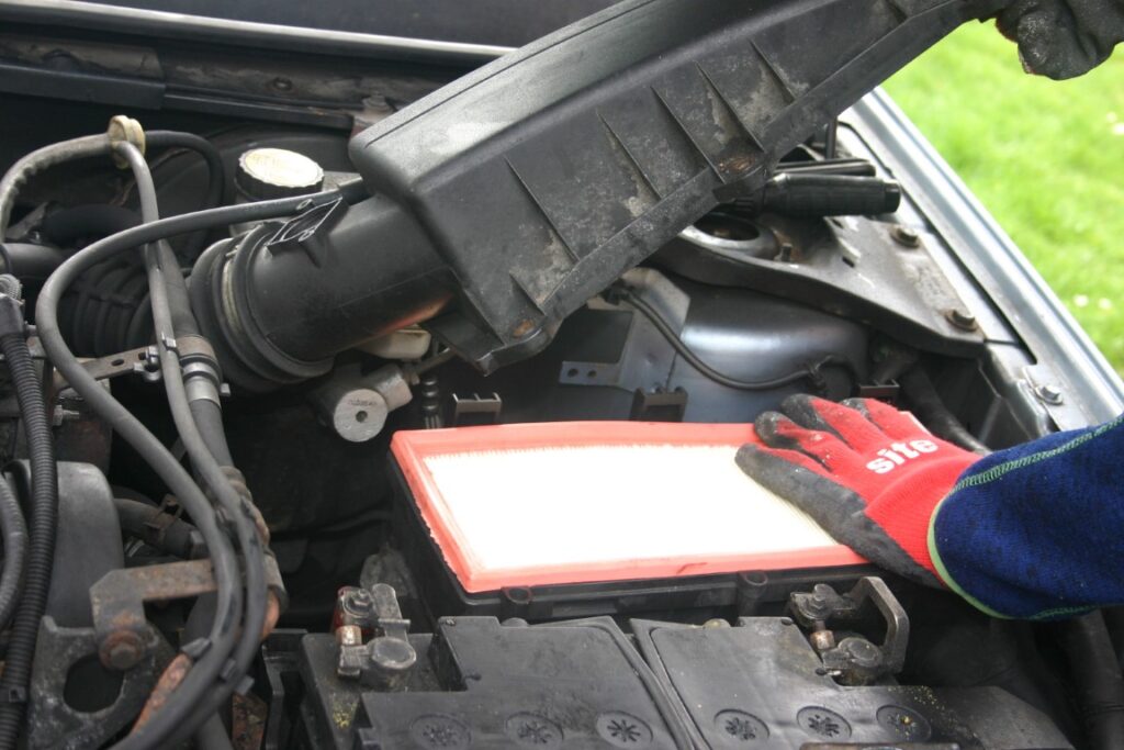
First open the bonet and locate the air filter housing inside the engine bay as shown with the black arrow:
Air filter housing
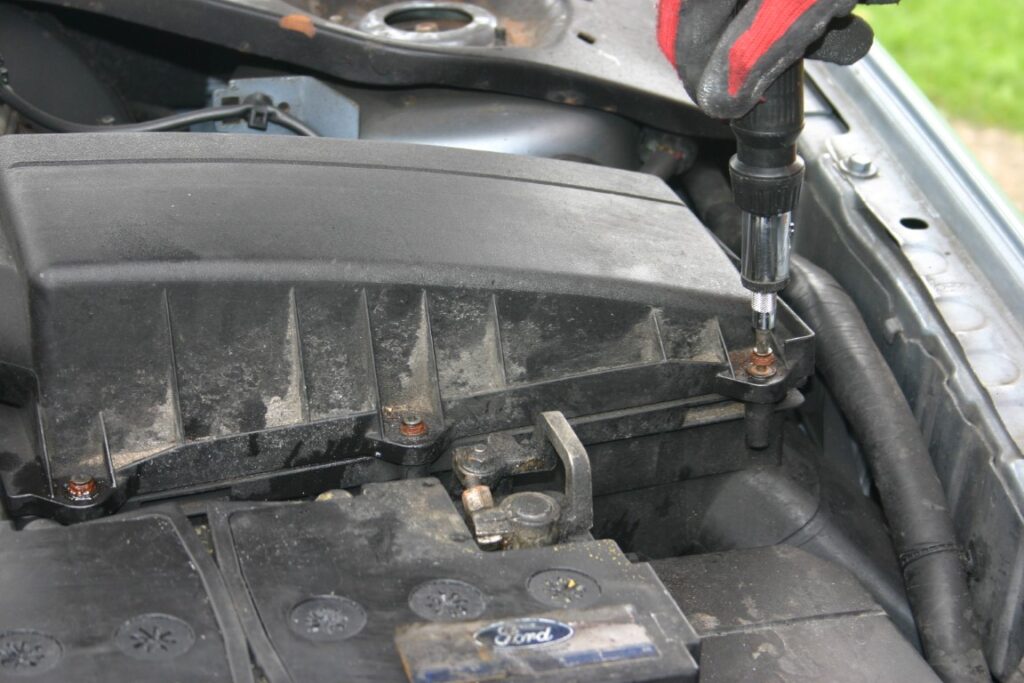
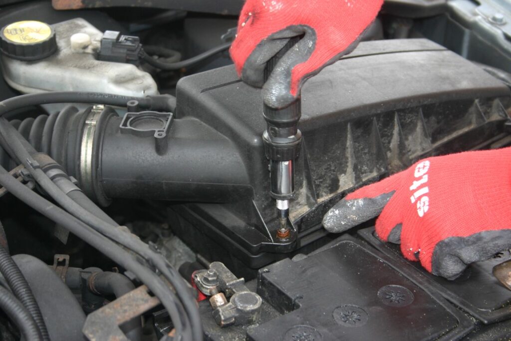
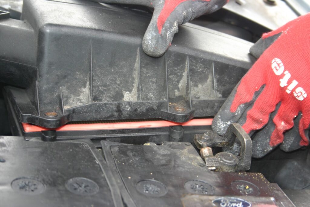
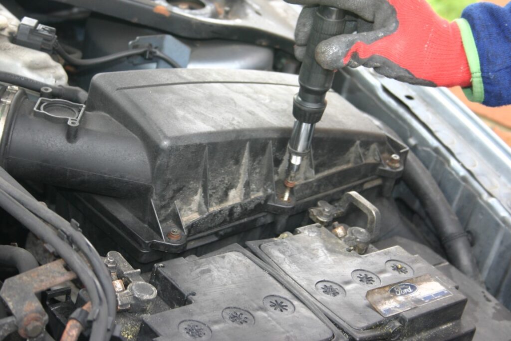
Open the screws surrounding the air filter housing:
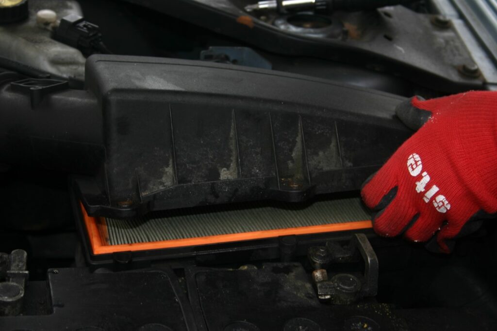
Pull open the air filter housing gently, making sure nothing else is in the way:
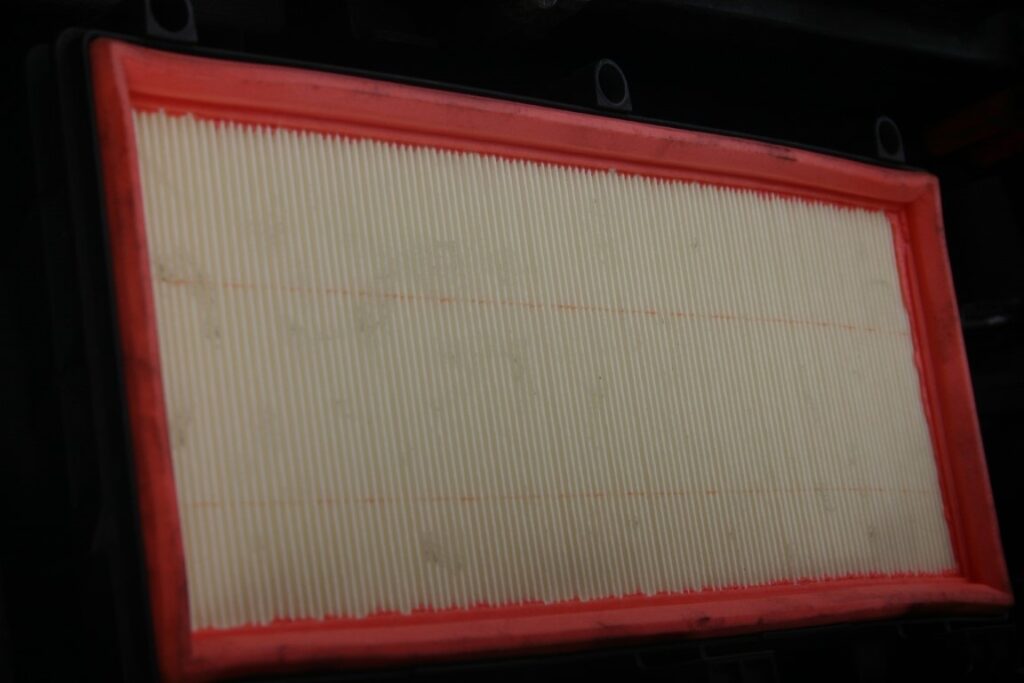
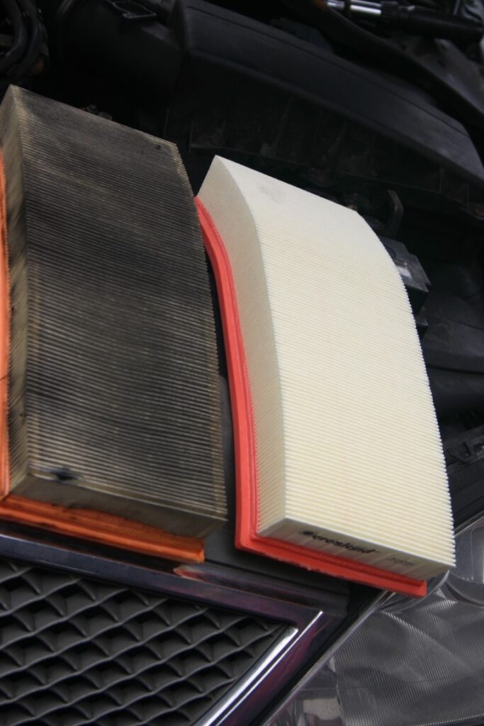
Comparison of the used and new air filters:
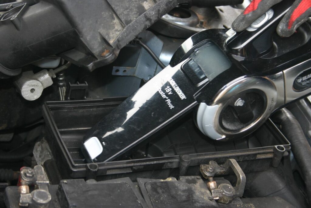
Clean any dirt from the air filter housing with a vacuum cleaner:
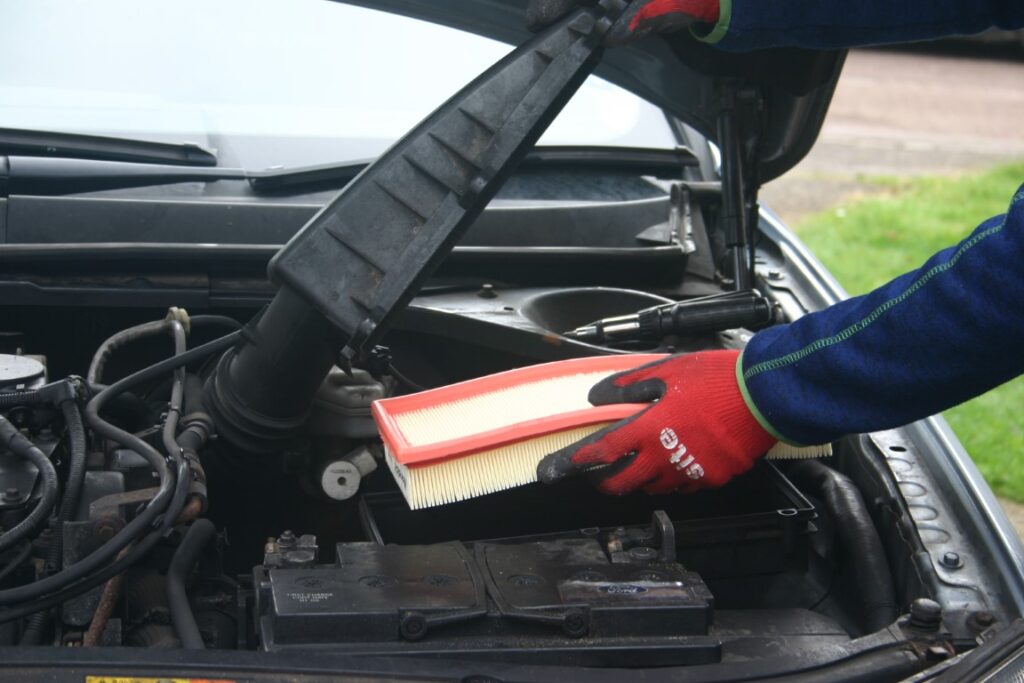
Repalce the air filter with a new one and make sure its snug fit:
Normally, it is advised to disconnect your car battery when one is not going use the car for a longer period. This is to prevent the battery getting drained and the car becoming useless upon your return.
Particularly with the BMWs without a manual lock, the Boot/Trunk comes with an electrical latch which can only be opened with its remote.
This means, once you disconnect the battery and close the Boot/Trunk, there is no direct way to open it when you want to reconnect the battery wire/lead.
I have seen many videos showing drilling hole through the rear seats to reach the latch from the inside of the car. There is no need to go to this extreme because BMW provides a very easy indirect way to open the Boot/Trunk even if car’s own battery is disconnected. Please let me explain with some photographs.
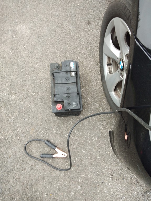
All you require is 12V DC battery, ideally another car battery. This does not have to be a brand new one but atleast which can provide a small amount of current to drive the electrical latch of the Boot/Trunk. Even a portable jump starter should work.
I chose to use an old used 12V car battery which I had to replace with new one because it had become weak and could not start my car’s diesel engine. I think any other 12V DC battery with sufficient current capacity should also be able to open the Boot/Trunk as I think it does not have to be a car battery. The following photo shows the old car battery that I had used.
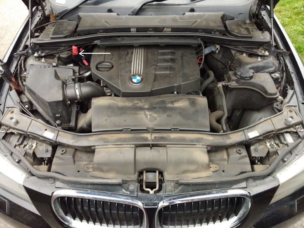
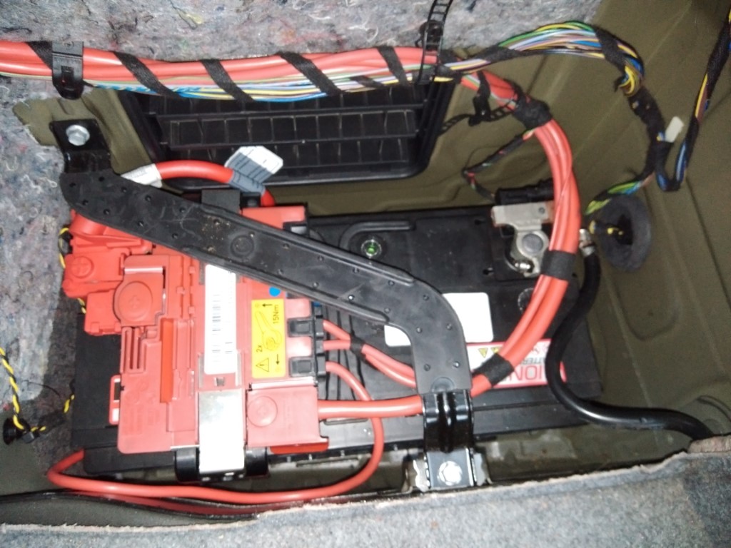
I hope you know how to open the driver side door manually using the physical key from the key fob. Then open the car bonet. The next thing you have to do is to locate a red capped protuding connector looking thing in your BMW’s engine bay as shown with an arrow in the following photo:
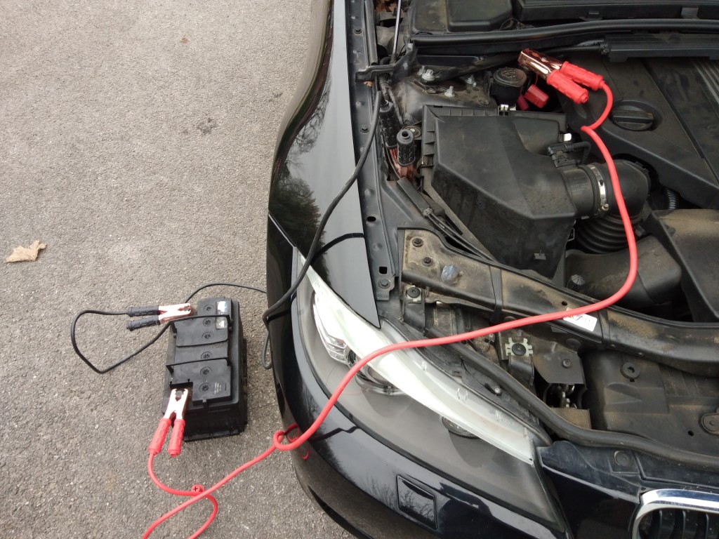
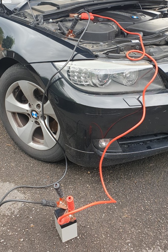
In fact, this connector is a positive terminal of the Car’s power supply. The body is a negative terminal. So, connect these car terminals to the battery terminals as shown in the following photo:
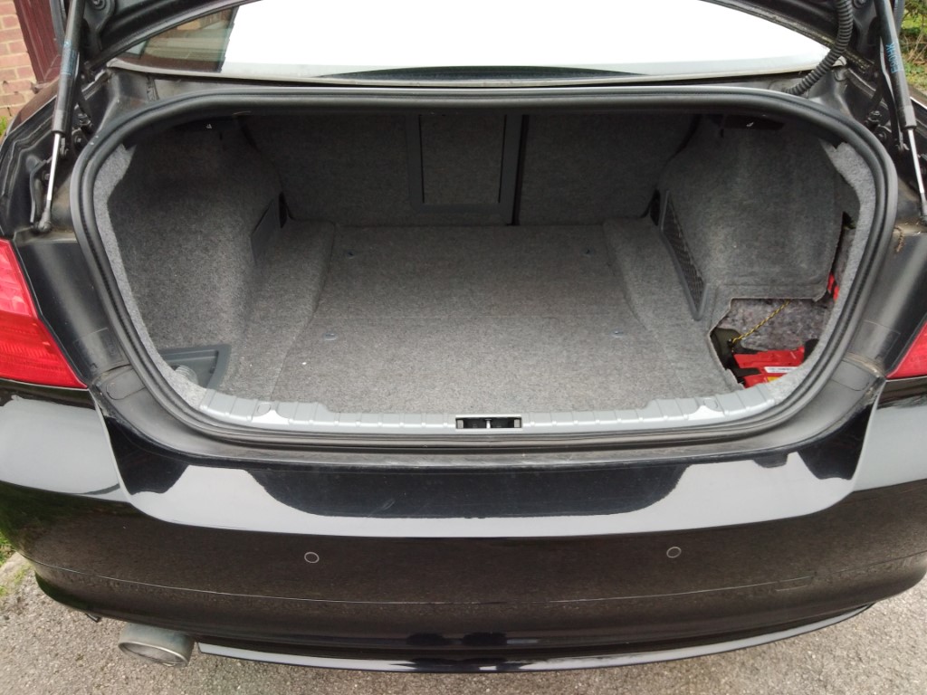
After these terminals are connected, now you can press your remote key fob boot/trunk open button. This should open the electrical latch of the boot and now you can open the boot/trunk as shown in the following photo:
Now, after you have opened the boot, first disconnect this external battery. Then reconnect the car’s own battery. If everything else is ok, then your car should function normally.
Until now I have been using my laptop without an external mouse. I now needed to use an external mouse for my work because the touch-pad and the buttons on the touch-pad slowed me down.
A while ago, I had purchased an off-the-shelf cheap lap-desk for my laptop which did not have space to put external mouse and mouse pad. This still cost me £10. So I did not want to spend more money to buy another one. Also, lap-desks with space for an external mouse were quite expensive and not normally easily available.
So that got me thinking, the aim was to figure out a quick, cheap (almost free) way to make a lap-desk with decent space to accommodate a mouse pad and external mouse. You may choose to not have the space for an external mouse. This Instructable shows you step by step how to make such a lap-desk from scrap laminate flooring.
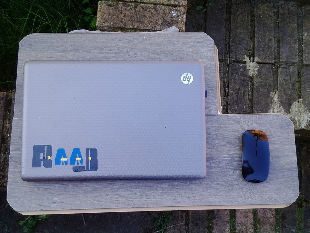
The picture on this page is of the finished lap-desk.
Materials and Tools
The aim is to make it almost free or extremely cheap. When I say cheap, definitely cheaper than the off-the-shelf one which had cost me £10.
Materials:
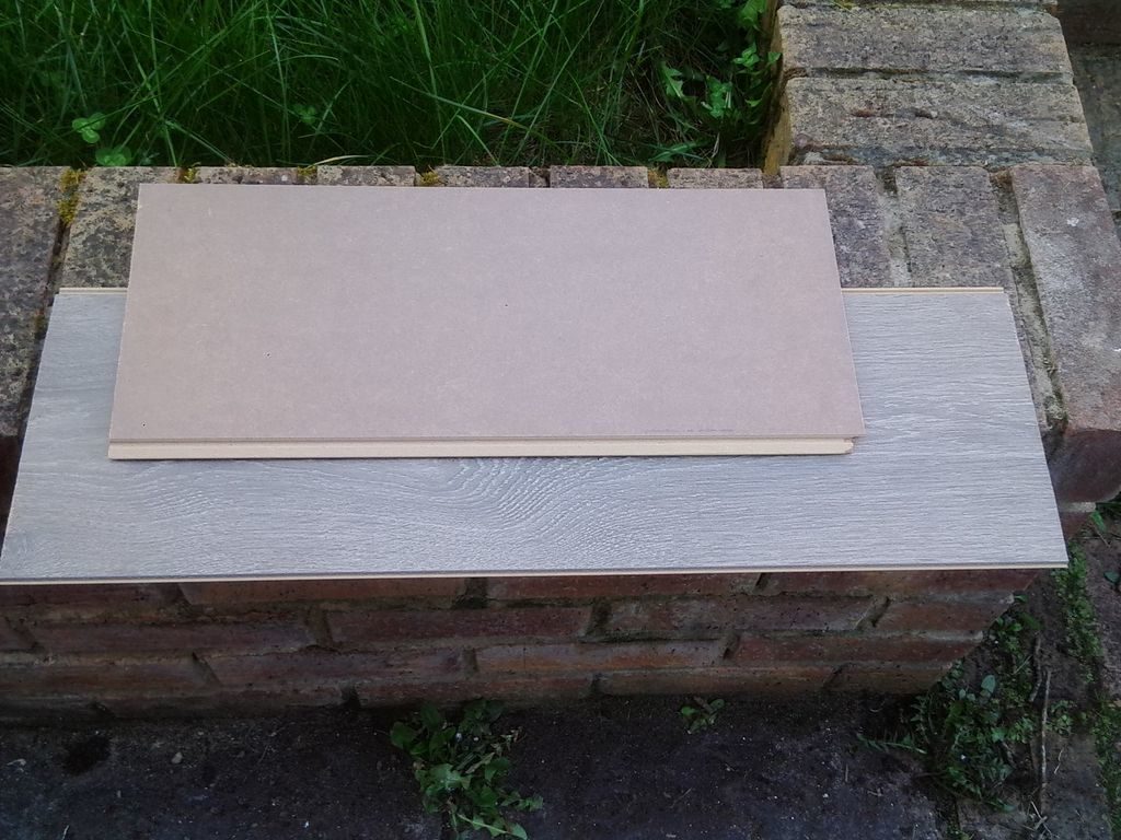
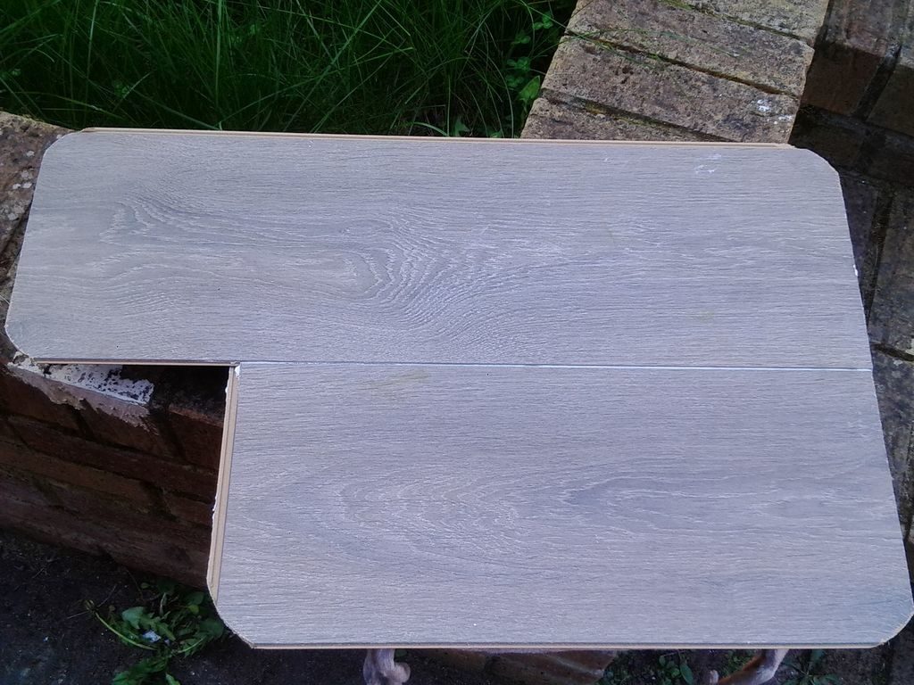
1) Scrap, unused, off-cut, reclaimed laminate floor board. You have freedom to choose whatever color you like. We need two pieces to click into one another so as to allow the width to fit the lap and so that you can rest a decent sized 15 inch laptop on it. You may measure the size (length and breadth) of your lap that you want to cover and the size of the laptop. One piece requires to be slightly longer than the other to allow the space for an external mouse. You may choose not to have space for an external mouse, in that case you should have both the cuts of the laminate of same size. Images show the cuts that I used.
2) Some form of wood/construction glue.
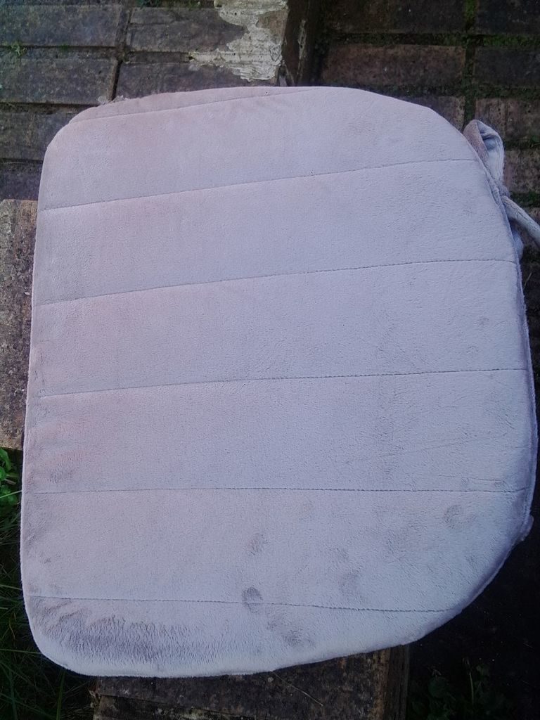
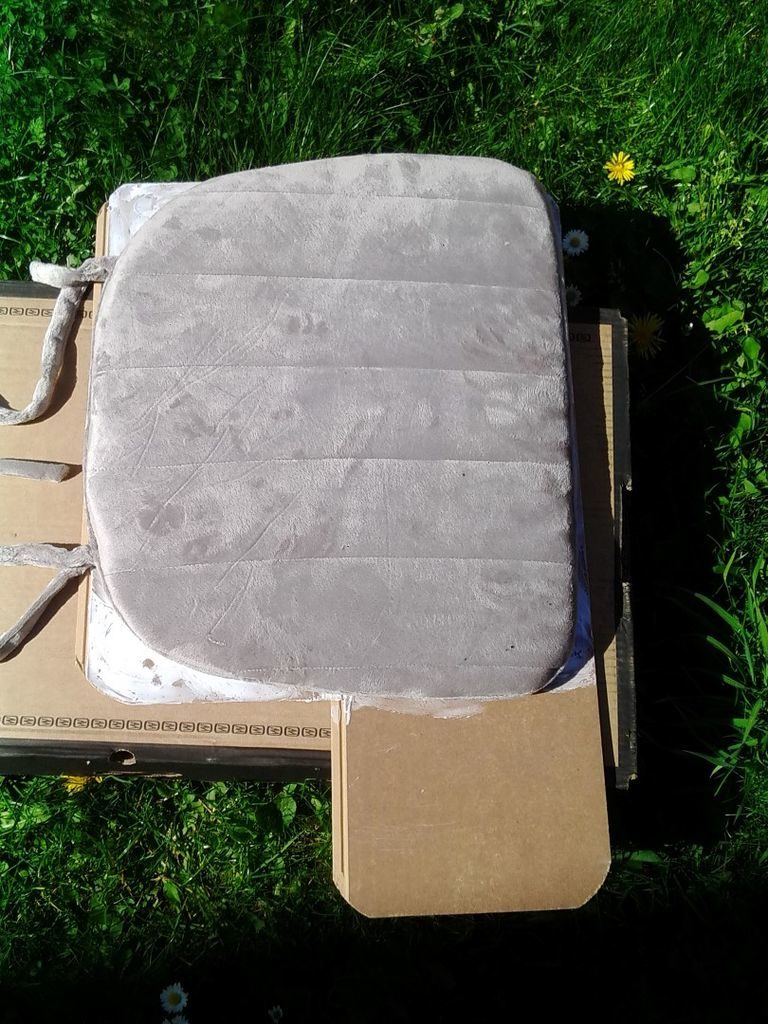
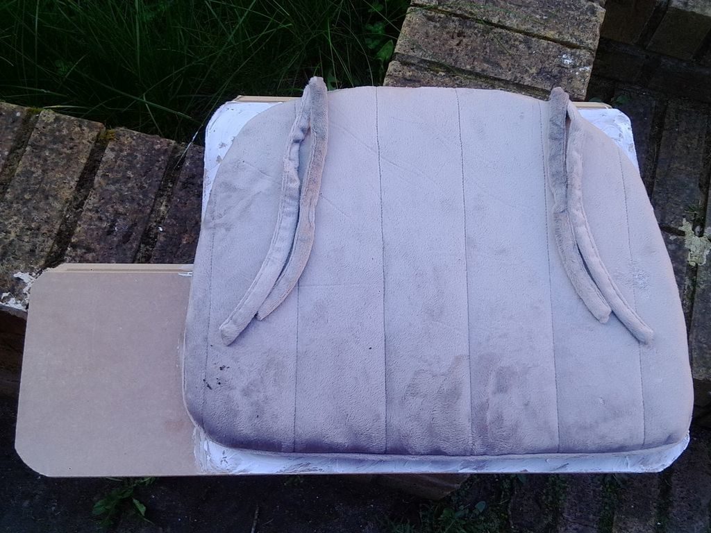
3) A chair cushion. The size would be to cover the lap area.
Tools:
1) Jig saw or hand saw or some saw to cut the laminate as necessary.
Joining the Two Offcuts of Laminate Flooring Boards
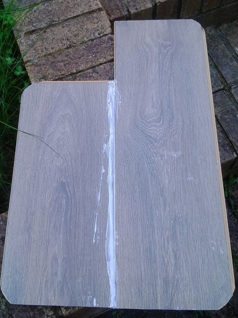
1) First of all, I cut and rounded the corners of the laminate boards as they can be quiet annoying when you use the lap-desk.
2) You may choose to trim the unused tongues on the side but I did not bother. As the idea was to save time and make it quick. Also time is money :).
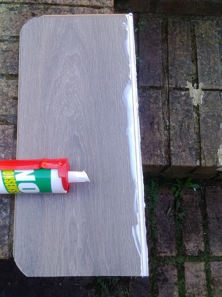
3) Apply the wood/construction glue into the tongue of the laminate board and then click the second piece into the first one as shown in the image.
4) Leave it for the glue to dry out.
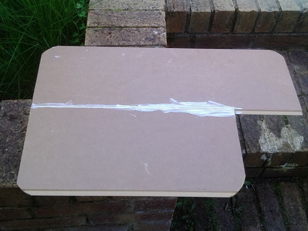
5) In case you would like to attach more support for the two boards, as
shown in the image, you can glue a couple of supporting laminate or wood pieces. You can use clamp to hold them until they are properly stuck and the glue has dried. Althought, the boards glued and dried properly should be strong enough to hold without requiring this step.
Attaching Seat Cushion
1) Apply glue on the back side of the composite laminate in order to attach the chair seat cushion.
2) Place the cushion on the glue, press it to make sure the cushion is attached properly.
3) Reverse the assembly and put some weight on top and leave it for the glue to dry out.
The idea behind the cushion is that it provides support and cushioning effect on the lap while resting at least 1 or 1.5 Kilo worth of laptop weight. Most of the off-the-shelf ones do come with some form of cushion. I already had a memory foam chair cushion and that is what I used. However you may choose whatever is available.
There is no step here. Just that after the glue is dried, the lap-desk is ready to be deployed 🙂 as shown in the image.