
Yet another voice controlled home automation system!
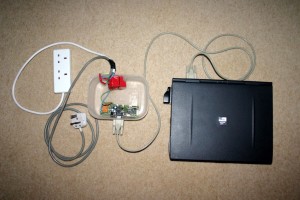
As shown in the picture, the system can control any electrical appliance, by turning ON or OFF, that is connected into the electrical socket. The system does this using bespoke voice commands. The system uses a micro-controller board (PIC or Arduino) and a PC/Laptop with the Microsoft Windows Operating System.
This project was featured on the front page of Instructables.com
http://www.instructables.com/id/Voice-Activated-Power-Sockets-Home-Automation/
And was short-listed in the quarter finals of the Hackaday-2014 competition
https://hackaday.io/project/1986-voice-activated-power-sockets-home-automation
Motivation
I always wanted to make a system that worked on my voice commands. I started working on this project to realize my dream to be able to control gadgets/appliances with my voice commands. I made this project at home from my electronics laboratory in my garage and in my holiday time and on weekends.
Step 1: Project Theme: ! (Re-Inventing the Wheel)
I strongly believe in not “re-inventing the wheel” therefore most of the components that I have used are off-the-shelf (Hw/Sw both). This enables anybody to create this project very quickly without requiring in depth technical knowledge about electronic circuits and without worrying about the complexity of speech recognition.
This project is more of an innovation hobby project. The components that I required to build a basic speech recognition based home automation system were a speech recognition software, a PC or an embedded computer with an internal or external microphone to run the speech recognition software, an electronic circuit to control the power to an electrical appliance or a gadget.
Step 2: System Design
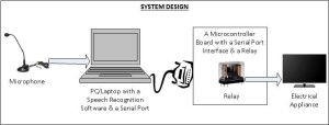
The way this automation system is designed and works is as shown in the figure. When a voice command (any voice command that I like) is uttered, it is recognized by a speech recognition software running on a PC with a microphone. The speech recognition software then invokes a ‘C’ program, i.e. Serial port driver, that sends a command over to the PC serial port to which a micro-controller board is interfaced. The micro-controller on the board runs a firmware that receives the command from the serial port and interprets it. The micro-controller then toggles an output pin which drives a transistor which in turn drives a relay. The relay then controls any appliance that is connected to it. The figure shows the complete system design.
Step 3: Finding the Right Speech Recognition System
The very first thing that I required was a speech recognition system that would allow me implement my own commands and train my voice on the same commands. In other words I wanted the functionality where the system would accept my own customized voice commands and upon recognizing the commands the system would then run an executable or a program that I have implemented. While I was looking for such system on the internet, I stumbled upon a PC based speech recognition system called “TAZTI”. I selected this software as the speech recognition front end is because it satisfied the main two requirements: firstly it allows the user to create their own custom voice commands and secondly the system allows user to run their own program or executable upon recognizing these commands. There are quite a few other useful features in the Tazti speech recognition software (can be obtained from their website www.tazti.com ). Older versions of the software were freeware but the current versions are paid however they do provide a trial version for 15 days.
Step 4: Interfacing with the PC
The second thing that I needed was a way to interface an electrical appliance with the PC using possibly the parallel or the serial or the USB port . So when a voice command is recognized in the PC a program would be executed which then sent a control command to the interfacing circuit to activate or de-activate a relay that controlled the electrical appliance or the gadget. I chose to use an off-the-shelf PIC micro-controller board that also had a relay and a serial port interface on the same board. You could use any such micro-controller board for an example Arduino.
While looking for such micro-controller board I came across PIC-MT a development board for 28 pin PIC microcontroller from Olimex (can be obtained from their website www.olimex.com ). This board comes with a Serial/RS232 interface which can directly be connected to a PC serial port and an on-board circuit with a relay. All the details about the board such as schematic/circuit diagram and user manual etc are available from their website. I used PIC 16F876A for my prototype and implemented the firmware for the micro-controller in ‘C’. I have also used the PIC boot loader and downloader software from Sparkfun (from www.sparkfun.com ). The boot loader allowed me to download the firmware in hex in to the program memory of the micro-controller over the serial port of the PC without requiring a proper PIC programmer and the special board socket for PIC programmers. Also this was carried out while keeping the micro-controller in the chip socket on the board, i.e. ICSP (In Circuit Serial Programming). Although I did have to program the boot loader for the very first time using the PIC programmer (PIC Start Plus or similar) into the micro-controller.
Step 5: PC Serial Driver/Client Program
I implemented a simple ‘C’ program (essentially a Serial/RS232 driver and a client program) for the PC which would send a control command over to the serial port to the PIC board whenever this program is executed. The PIC serial server program would then listen to the commands arriving on the serial port and upon recognizing a control command it would perform a task(s) such as turning ON the relay or turning OFF the relay.
The attached ‘C’ Serial/RS232 driver/client program sends command word 27 to the PIC board. I programed the voice command to be “TV ON”. This code has been successfully tested on Windows XP. For the voice command “TV OFF” the command word was 28. This ‘C’ program is in older style, shown here as an example, more modern Win32 user mode driver program could easily be written using Windows API for accessing serial port.
Step 6: PIC Firmware (Serial Port Server Program)
The firmware is essentially a server program running on the board, which listens to commands arriving via the serial port from the PC and executes the commands i.e. Toggle a port pin and drive a relay. You could make the controller carry out anything you like.
I would like to show the part of the PIC-16F876A firmware that receives the command from the PC over the serial port and toggles a pin which then turns the relay ON or OFF. The following code has been extracted from a larger working firmware program so it has not been tested in its isolated form.
Step 7: PIC Board
Since the PIC-MT board has many other features, If you would like to make your own PIC micro-controller board to carry out just the above functionality all you require is following, you will need a PIC programmer to program your PIC:
1) PIC16F876A
2) A crystal oscillator: 20MHz
3) 2 Capacitors: 22pF
4) 1 Transistor to drive the relay
5) 1 Relay
6) 5V supply to the PIC controller.
This can be achieved using a dedicated power supply such as wall adapter or make your own using the 7805 regulator Integrated Circuit.
7) A way to interface with the PC serial port. There are several ways to achieve this, for more details on how to implement the following please use your favorite search engine:
(7.1) MAX232 Serial Driver/Receiver Integrated Circuit
(7.2) FTDI- FT232R USB to UART Integrated Circuit
(7.3) A USB dongle that converts USB to Serial and provides you with an emulated Serial port.
(7.4) A two transistor level converter circuit for directly interfacing with the PC serial port.
Similarly you may choose to use an Arduino board instead.
Step 8: Even Safer Design (Paranoid Safety Level!)
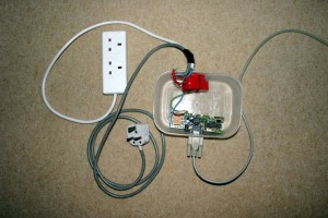
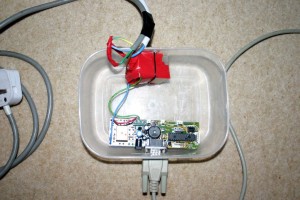
Additionally in order to make the design even safer (with respect to dealing with the 230V AC supply) I added a second relay. The reason is that if I had used the on-board relay full 230V AC would be arriving on the relay terminals on the board. Instead a second relay is driven using the relay that is on the board. As you can see in the images the on-board relay is orange in color whereas the second relay is separate to the board and has Red tape over it. So whenever the relay on the board is driven it provides supply to the external relay turning the second relay ON or OFF.
Step 9: Going Wireless!
The main idea is to make the interfacing between the computer and the micro-controller board wireless. It is important to know that there are quite a lot of very cheap different types of off-the-shelf wireless modules available. Many of these modules provide simple serial communication protocol the RS232 over a wireless protocol. For an example, such Bluetooth module can provide serial communication over Bluetooth protocol. Similarly modules providing Serial communication protocol over Wifi and RF are also available. Let’s take an example of Bluetooth protocol for making the home automation system wireless.
1) For the micro-controller board: You can get one of the Bluetooth modules with Serial interface and connect the RX, TX and GND pins to the micro-controller serial interface pins. You need to take care of the voltage levels while interfacing with the micro-controller or a micro-controller board, most of these wireless modules can work with 5 or 3.3V.
2) For a PC you could use a Bluetooth-USB dongle that emulates serial port over Bluetooth. This means when you connect the dongle to your PC, it will show up as a Serial/COM port. Then it is quite simple, you can use the same ‘C’ application and same speech recognition software as mentioned in this project to send command to the Bluetooth dongle via the emulated COM port thus making this home automation system wireless. Very simple.
I leave it upto you to find out various ways to control this home automation system with countless Bluetooth enabled devices.
Step 10: General List of Components
The following is a general list of components, just to give you an idea to what is required.
1 × Windows PC/Laptop with Internal/External Microphone
1 × Serial – RS232 cable
1 × Olimex PIC-MT, 28 pin PIC or similar micro-controller development board with onboard relay & serial port
Alternatively an Arduino board with a shield having 230V Relay.
1 × 12V DC power supply to power the micro-controller board
1 × Tazti or similar speech recognition software
1 × AC – 230 V power socket with cable (to interface with the relay)
1 × AC – 230 V power plug with cable (to interface with relay)
