
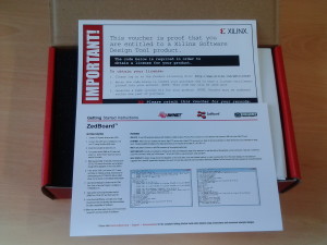
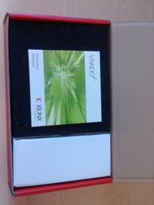
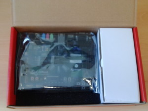
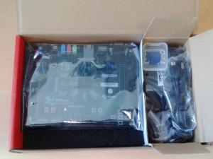
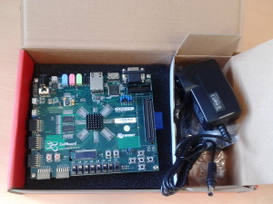
I purchased my very own Zedboard in order to work on some of the cool FPGA stuff at my home in my Electronic Lab. This board has the state-of-the-art Xilinx Zynq 7020 FPGA. Here I show unboxing the contents of the Zedboard that I received.

I ran a campaign on the kickstarter.com in order to mass manufacture this device however due to insufficient marketing the campaign did not meet its goal. Nevertheless I gained valuable experience and feedback from people around the world. Currently I am improving EkZee based on the feedback. And I think now I know what to do in order to make such a crowd funding campaign a success. So this proves one of the well known NLP presuppositions: There is no failure, only feedback :).
https://www.kickstarter.com/projects/1675461711/ekzee-a-portable-gadget-to-remove-viruses-from-usb
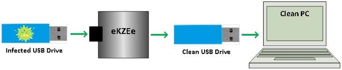
EkZee is a portable, pocket-sized, standalone electronic device which detects and deletes executables that can contain virus on USBs

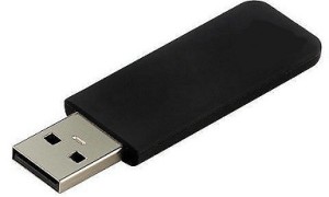
This USB stick could infect your computer with viruses.
Don’t worry help is at hand! All you need is EkZee (Patent Pending) and your worries are over. Simple to use, deadly effective (for computer bugs/viruses).
EkZee is a pocket-sized and standalone electronic device which detects and deletes all the executables that can contain malware (short for malicious software such as virus and spyware) from the USBs. EkZee is a patent pending technology.
It is often too late to use the conventional anti-virus software in the computer to disinfect the infected USB flash drive. This is due to the fact that many viruses can easily circumvent or infect the pre-installed anti-virus software in a PC ultimately rendering the anti-virus systems ineffective.
So you can not risk cleaning the USBs using your PC when you do not know what it is infected with. Many times malware can get into your computers and spread infection as soon as USBs are plugged in.
If you have any USBs you need to Get the EkZee Habit
On a single press of a button EkZee detects and pre-emptively deletes all the executables that can contain malware such as viruses and spyware from the USB flash drive prior to insertion into a computer.
This is simple, cheap but powerful way of preventing malware contagion carried by team members; particularly those who are often working on-the-move; attending external meetings and wish to be able to exchange documents with clients and collaborators readily using a USB – EkZee frees them to do so free from any risk or worry.
So please EkZee your USB before using it on your computer or lending it to anyone to use on their computer – EkZee USBs every time before use; the EkZee Habit; is simple and essential for cyber security.
EkZee is a standalone independent device and does not require a conventional PC to carry out its operation.
EkZee remains impenetrable to malware so it cannot get infected while carrying out its operation. This is because EkZee ‘s own functional code is stored in its unmodifiable internal architecture.
EkZee does not affect data files such as word processor, PDF, image, video files and spread-sheets etc.
Computers that control critical infrastructure such as power stations, gas stations, utilities, nuclear reactors, space stations and other industries are prone to virus infection by removable storage devices. This is because the transport of data in and out of these computers is typically carried out using USBs which can act as malware carriers rapidly spreading the infection across the organisation.
Malware can steal personal information and passwords. Malware can remotely control your PC, transmit confidential information from your PC, download new malware and cause significant and sometimes irreversible losses and damage to enterprise reputation and business, critical infrastructure such as power stations, gas stations, industries and utilities etc. which are typically controlled by computers.
“Malware, short for malicious software, is software used or programmed by attackers to disrupt computer operation, gather sensitive information, or gain access to private computer systems.’Malware’ is a general term used to refer to a variety of forms of hostile or intrusive software. Malware includes computer viruses, spyware, adware and other malicious software.” (Source: Wikipedia)

USB flash drives are widely used as a convenient, portable, high storage and cost-effective means of data transfer. USBs have no built-in protection against malware.
Therefore USBs are susceptible to becoming infected by malware and could easily spread the infection to other computers.

When a USB flash drive is connected to an infected PC, the virus from the infected PC propagates into the flash drive and infects it.
The infected USB flash drive becomes a carrier and in turn spreads the virus into other PCs when the drive is plugged into the PCs to transfer or copy any data.
Similarly, other USB flash drives are in turn infected further once they access the infected PC. The infected PC then infects other computers on the network and in this way the infection rapidly spreads into many computers and USB flash drives.
The malware which in this way finds its way into the heart of the enterprise then can start stealing information and disturbing it as well as potentially sabotaging enterprise devices and operations including business process and mission critical structures.
EkZee very cost-effectively and rapidly breaks the chain of malware infection from USB to personal computers (PC) and to other USBs and stops them all becoming carriers spreading the malware far and wide within and beyond the organisation.
At present we have our own proprietary way of malware detection and removal in EkZee.
EkZee currently supports USBv1.1 and USBv2 based flash drives and memory cards (Requires a separate USB memory card reader to read Secure Digital – SD, CompactFlash).
Power Requirements
EkZee is currently powered by a standard USB port on a PC or a laptop.
We will supply a USB to mini-usb cable with every EkZee unit. EkZee has a mini usb connector to which the supplied cable is connected to power the EkZee unit. This makes EkZee a battery-less device and hence less expensive to produce, sell and run.
Supported Filesystems
EkZee currently supports FAT12, FAT16 and FAT32 file systems on USB flash drives and memory cards having a single partition (typical).
EkZee has been successfully tested to work with flash drives upto sizes of 128GB.
Detected Malwares
EkZee comes preloaded with definitions to detect more than 100 Microsoft Windows Operating System (trademark of Microsoft Inc.) based executables that can contain malware. EkZee can also detect hidden executable files. EkZee has been tested with real malware samples as well.
Definitions and Firmware Update
We are planning to provide updates for EkZee firmware and malware definitions (a subscription based service) on our website. Since EkZee requires additional hardware and firmware support for the updates, we are exploring potential solutions for the implementation of the update process within EkZee.
Disclaimer & License Agreement (Limitation of Liabilities)
We have carried out extensive testing to make sure EkZee performs as specified without affecting any of the non-executable user data. However, by buying (backing) EkZee the buyer (here Kickstarter backer) agrees that in no event shall the inventors/suppliers/manufacturers/creators of EkZee be liable to the buyer (here Kickstarter backer) for any (incidental or accidental or consequential or otherwise) damage or loss of data or program or else as a result of using EkZee. Supplier’s (here Creators of EkZee) maximum liability under this contract shall be limited to the purchase price of the Product (here EkZee). Furthermore, we reserve the right to alter specifications, features and products at any time without prior notice.
Full license agreement will be published on EkZee website. This is Inline with the disclaimers and license agreements other anti-virus vendors have on their websites.
It all began with a thought when I visited India in 2011. While downloading pictures from a memory card removed from a camera the anti-virus in my computer gave a warning that there was a virus in the memory card. This triggered a chain of thought in my mind. The camera belonged to someone whom I knew, a local person in India. The only way a virus could have entered into the memory card of the camera could have been while downloading pictures to a computer which must have been infected with a computer virus. I thought if I can find a way to remove viruses from the memory card i.e. a removable storage devices, the spread of such viruses/malware could be easily stopped. Also the virus removal device has to be a separate standalone device which should function outside of any personal computer. Such a device must not get infected while carrying out its operation. Also it must not affect other normal data files like images, documents etc.
And this is how the original idea of EkZee was born!
After initial thought about EkZee, we wanted to create a proof-of-concept. So we first created the EkZee prototype on a breadboard by wiring a few components and a high-performance microprocessor. The following two images show the very first EkZee prototype wired on the breadboard.

EkZee Circuit on a Breadboard, The Very First EkZee
Afterwards, in order to reduce the power consumption of the EkZee circuit, we replaced the previously selected high-performance microprocessor with a low-power and a low-performance one.
Further, in order to reduce the physical size of the circuit we decided to create the EkZee prototype on a general purpose printed circuit board.
The following two images show EkZee prototype embedded on a general purpose PCB.


PCB Design & Layout
In order to reduce the physical size even further and make EkZee extremely small so it could fit perfectly to a user’s pocket almost like a USB, we decided to use Surface Mounted (very tiny) components. These components are extremely difficult to solder onto a general purpose PCB. Hence we created our first Printed Circuit Board (PCB) design and layout for the EkZee prototype. We have had the above PCB manufactured professionally and have successfully tested the functionality. The following sections and images show pictures of EkZee prototype and its functionality.
Manufactured PCB Prototype


EkZee Prototype
We would like to show you the images of our EkZee prototype. We have successfully tested EkZee on various USB flash drives and memory cards.

As you can see in the above image, the actual size of EkZee circuit is quite small but we have used an off-the-shelf enclosure for the prototype which makes it look bigger than it need be but the future prototypes will be provided in custom-sized packaging that allows the EkZee unit to be offered in small match box or even smaller sizes.


What you see in the above photos is an actual working prototype. We’ve developed several prototypes that we’re using for testing and for development. Our Hardware design is complete and our software is under beta test at the moment but it is very stable and we are very close to finalizing so that our EkZees will soon be ready for shipping to our users.
Current Enclosure Design
We have designed a plastic enclosure for the 1st Batch of EkZees. The designed enclosure is such that no screws are required to close the case which reduces the cost of production. The top and bottom ends simply click in.


The image of the British pound coin in the following image serves to show the size of the final EkZee.

I would like to share with you a true story of my job interview at the Imperial College London. Yes, the world renowned Imperial College London. This was the year 2010. I applied for a position of researcher at the Imperial College London.
By sharing this, I hope to inspire the engineers particularly from Gujarat and India who at times, like me, have felt inferior, while even thinking to compete with other engineers from IITs, MITs, Cambridges, Oxfords, Standfords, Imperial Colleges, of the world. By reading this article you have read and understood the Disclaimer.

I went to the Imperial College London to give the interview and carried with me the Voice Activated Power Sockets Home Automation system (described in detail here http://www.technikal.net/blog/voice-activated-power-sockets-2/ ) that I had designed and developed at home, thinking I might get an opportunity to demonstrate what I do and could do.
First I was asked to present my previous research work to the panel of academics and professors. The presentation and personal interview went ok. At the end of the interview, while the interview panel was wrapping up, I approached the chief interviewer, the professor, and asked him if he had a few minutes as I wanted to demonstrate to him something that I had developed. The professor agreed to give me a few minutes. So very quickly I dug into my rucksack and brought out my voice activated home automation system. I then powered up everything and issued a speech command “Lights ON” and the connected bulb lit up. Then I commanded the system “Lights Off” and the bulb switched off.
After seeing this, the professor became very interested in my work and my abilities to make things. I informed him that I have been playing with electronic circuits since I was a child. I have been very fond of making electronic circuits and “making things happen”. The professor replied, “I understand, since you like to make things, I would like to offer you a challenge and if you accept the challenge then we will leave this interview aside and the outcome of your interview will be decided based on how you perform in the challenge”.
I was confident in myself and my knowledge and skills so I accepted the challenge without knowing what it was going to be. The professor then disclosed the challenge to me and said, it would be to design an electronic system that would measure and log velocities of two wheels mounted on an axle at each of its ends without physically touching the wheels (i.e. non-contact). I was given 3 weeks by the professor to make such a system and demonstrate it to him. The professor offered me to pay all the expenses.
I went home and thought about the challenge. Before starting to work on the challenge I emailed the professor with the specification of the challenge to confirm with him whether I understood the challenge correctly.
This is what I wrote:
“Just to clarify if I have understood your challenge clearly, so please let me put it into words.
There are two wheels which are mounted on an axle and they move in straight line without steering ability. I should make a non-contact electronic sensing device which would measure each wheel’s velocity separately. This will enable the calculation of velocity difference when the wheel axle assembly moves around a corner where one wheel moves slowly compared to the other.
Typically, cars are front wheel steered and rear wheels are fixed and move in straight line. Around corners, car’s rear wheels move with different velocity to each other.“
In his reply the professor agreed and also informed me that I should make the system such that it can make the real-time contact-less sensing with a good way of logging or real-time wireless transfer of the data.
I then started working on the challenge. The important thing in the challenge was to find out a non-contact way to measure the velocity of the wheel. The thought immediately came to my mind was that I needed an encoder however the professor wanted to test my knowledge of Electronics and I wanted to demonstrate my skills so I decided to design and develop my own encoder with a separate optical or magnetic sensor. At the same time, I quickly offered the first solution using bicycle computers.
Then I bought a test platform, a remote controlled monster truck to test my system on it. I designed and developed two optical sensors (one for each wheel) that worked on pulse generation and counting, from scratch. I interfaced the sensors with a micro-controller board. I developed the firmware that logged the velocity data of two wheels into its EEPROM data memory. I also developed a PC based driver that communicated with the micro-controller board over a USB interface and downloaded the logged data on a press of a single button. All of these things I completed it in my free time at night and on a weekend at home in just few days.
I went back to the Imperial College London to demonstrate the system. After reaching there, I took my laptop and the remote control monster truck. I powered the system and drove the monster truck on the floor of the professor’s office. The professor measured the distance roughly and timed the movement of the truck with his watch. The professor also stopped the truck with his foot to generate varying velocity data. Then I downloaded all the stored velocity data into my laptop and gave the data to the professor in a memory stick. The professor plotted a graph out of the data and the graph clearly showed the velocity and the variation in the velocity correctly as he had roughly estimated it to be.
The professor was very impressed with everything and offered me the position. Unfortunately due to few critical reasons I could not accept the position.
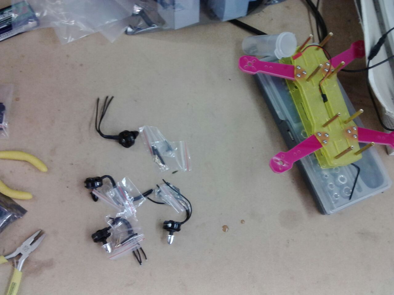
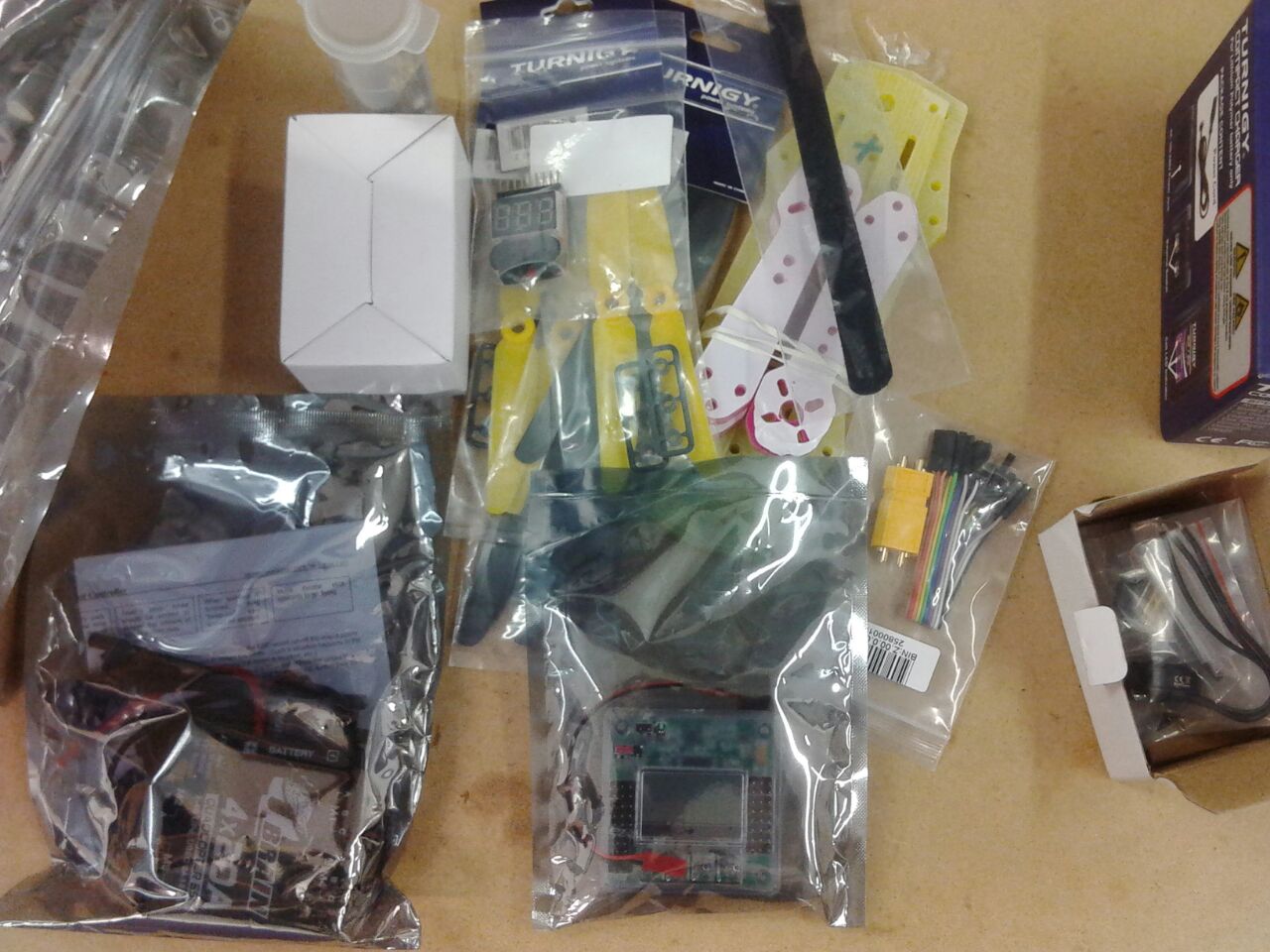
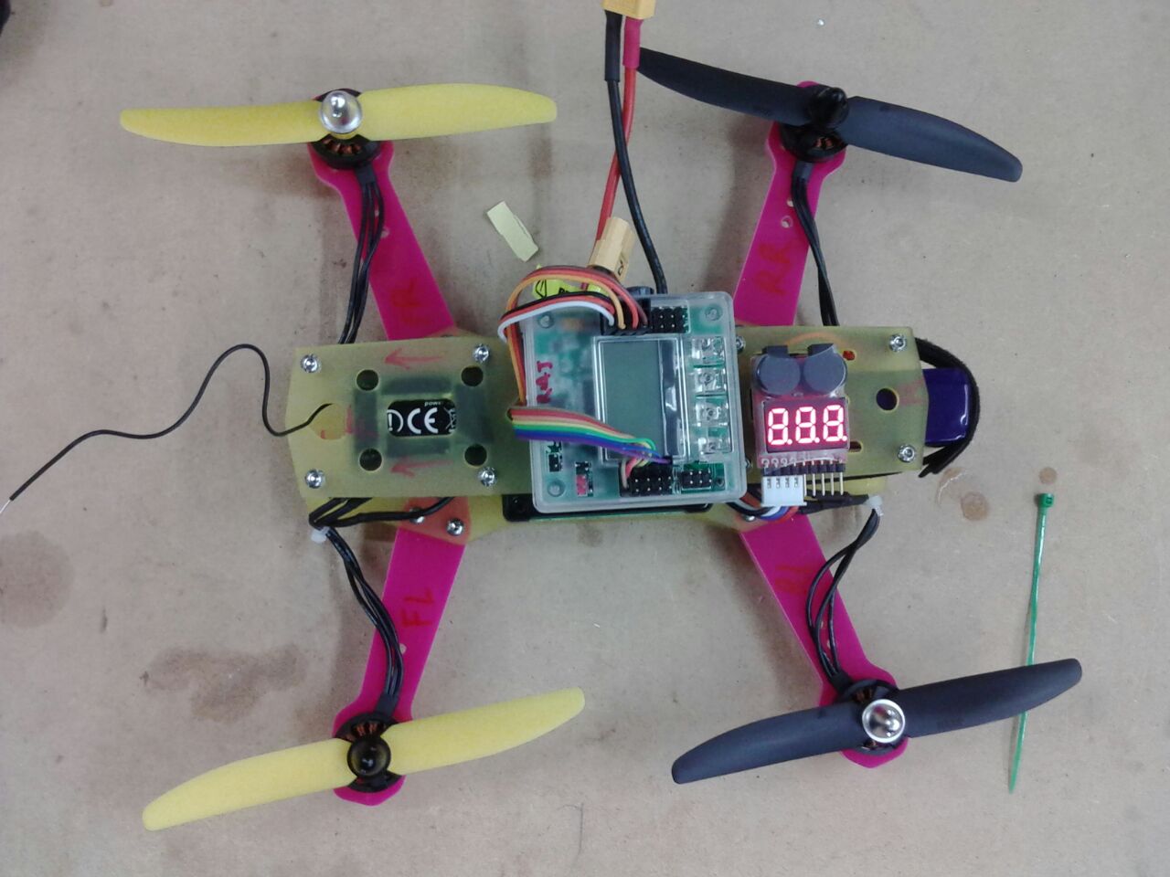
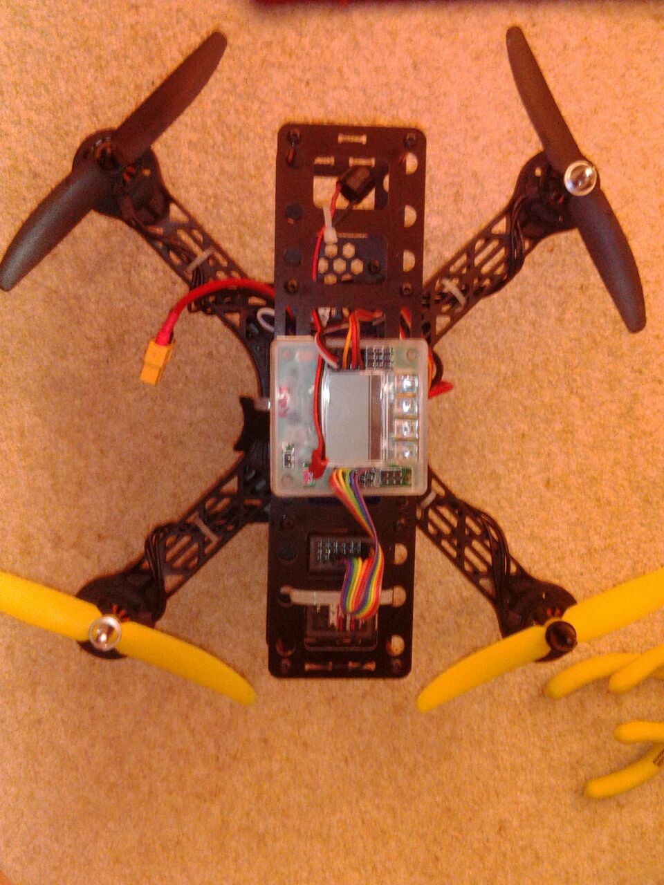
Sharing with you the first flight of the first quad-copter that I ever built from scratch at my home lab in my garage.
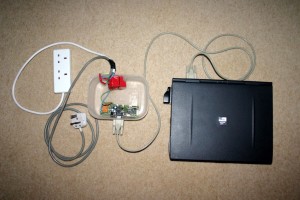
As shown in the picture, the system can control any electrical appliance, by turning ON or OFF, that is connected into the electrical socket. The system does this using bespoke voice commands. The system uses a micro-controller board (PIC or Arduino) and a PC/Laptop with the Microsoft Windows Operating System.
This project was featured on the front page of Instructables.com
http://www.instructables.com/id/Voice-Activated-Power-Sockets-Home-Automation/
And was short-listed in the quarter finals of the Hackaday-2014 competition
https://hackaday.io/project/1986-voice-activated-power-sockets-home-automation
Motivation
I always wanted to make a system that worked on my voice commands. I started working on this project to realize my dream to be able to control gadgets/appliances with my voice commands. I made this project at home from my electronics laboratory in my garage and in my holiday time and on weekends.
Step 1: Project Theme: ! (Re-Inventing the Wheel)
I strongly believe in not “re-inventing the wheel” therefore most of the components that I have used are off-the-shelf (Hw/Sw both). This enables anybody to create this project very quickly without requiring in depth technical knowledge about electronic circuits and without worrying about the complexity of speech recognition.
This project is more of an innovation hobby project. The components that I required to build a basic speech recognition based home automation system were a speech recognition software, a PC or an embedded computer with an internal or external microphone to run the speech recognition software, an electronic circuit to control the power to an electrical appliance or a gadget.
Step 2: System Design
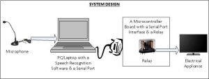
The way this automation system is designed and works is as shown in the figure. When a voice command (any voice command that I like) is uttered, it is recognized by a speech recognition software running on a PC with a microphone. The speech recognition software then invokes a ‘C’ program, i.e. Serial port driver, that sends a command over to the PC serial port to which a micro-controller board is interfaced. The micro-controller on the board runs a firmware that receives the command from the serial port and interprets it. The micro-controller then toggles an output pin which drives a transistor which in turn drives a relay. The relay then controls any appliance that is connected to it. The figure shows the complete system design.
Step 3: Finding the Right Speech Recognition System
The very first thing that I required was a speech recognition system that would allow me implement my own commands and train my voice on the same commands. In other words I wanted the functionality where the system would accept my own customized voice commands and upon recognizing the commands the system would then run an executable or a program that I have implemented. While I was looking for such system on the internet, I stumbled upon a PC based speech recognition system called “TAZTI”. I selected this software as the speech recognition front end is because it satisfied the main two requirements: firstly it allows the user to create their own custom voice commands and secondly the system allows user to run their own program or executable upon recognizing these commands. There are quite a few other useful features in the Tazti speech recognition software (can be obtained from their website www.tazti.com ). Older versions of the software were freeware but the current versions are paid however they do provide a trial version for 15 days.
Step 4: Interfacing with the PC
The second thing that I needed was a way to interface an electrical appliance with the PC using possibly the parallel or the serial or the USB port . So when a voice command is recognized in the PC a program would be executed which then sent a control command to the interfacing circuit to activate or de-activate a relay that controlled the electrical appliance or the gadget. I chose to use an off-the-shelf PIC micro-controller board that also had a relay and a serial port interface on the same board. You could use any such micro-controller board for an example Arduino.
While looking for such micro-controller board I came across PIC-MT a development board for 28 pin PIC microcontroller from Olimex (can be obtained from their website www.olimex.com ). This board comes with a Serial/RS232 interface which can directly be connected to a PC serial port and an on-board circuit with a relay. All the details about the board such as schematic/circuit diagram and user manual etc are available from their website. I used PIC 16F876A for my prototype and implemented the firmware for the micro-controller in ‘C’. I have also used the PIC boot loader and downloader software from Sparkfun (from www.sparkfun.com ). The boot loader allowed me to download the firmware in hex in to the program memory of the micro-controller over the serial port of the PC without requiring a proper PIC programmer and the special board socket for PIC programmers. Also this was carried out while keeping the micro-controller in the chip socket on the board, i.e. ICSP (In Circuit Serial Programming). Although I did have to program the boot loader for the very first time using the PIC programmer (PIC Start Plus or similar) into the micro-controller.
Step 5: PC Serial Driver/Client Program
I implemented a simple ‘C’ program (essentially a Serial/RS232 driver and a client program) for the PC which would send a control command over to the serial port to the PIC board whenever this program is executed. The PIC serial server program would then listen to the commands arriving on the serial port and upon recognizing a control command it would perform a task(s) such as turning ON the relay or turning OFF the relay.
The attached ‘C’ Serial/RS232 driver/client program sends command word 27 to the PIC board. I programed the voice command to be “TV ON”. This code has been successfully tested on Windows XP. For the voice command “TV OFF” the command word was 28. This ‘C’ program is in older style, shown here as an example, more modern Win32 user mode driver program could easily be written using Windows API for accessing serial port.
Step 6: PIC Firmware (Serial Port Server Program)
The firmware is essentially a server program running on the board, which listens to commands arriving via the serial port from the PC and executes the commands i.e. Toggle a port pin and drive a relay. You could make the controller carry out anything you like.
I would like to show the part of the PIC-16F876A firmware that receives the command from the PC over the serial port and toggles a pin which then turns the relay ON or OFF. The following code has been extracted from a larger working firmware program so it has not been tested in its isolated form.
Step 7: PIC Board
Since the PIC-MT board has many other features, If you would like to make your own PIC micro-controller board to carry out just the above functionality all you require is following, you will need a PIC programmer to program your PIC:
1) PIC16F876A
2) A crystal oscillator: 20MHz
3) 2 Capacitors: 22pF
4) 1 Transistor to drive the relay
5) 1 Relay
6) 5V supply to the PIC controller.
This can be achieved using a dedicated power supply such as wall adapter or make your own using the 7805 regulator Integrated Circuit.
7) A way to interface with the PC serial port. There are several ways to achieve this, for more details on how to implement the following please use your favorite search engine:
(7.1) MAX232 Serial Driver/Receiver Integrated Circuit
(7.2) FTDI- FT232R USB to UART Integrated Circuit
(7.3) A USB dongle that converts USB to Serial and provides you with an emulated Serial port.
(7.4) A two transistor level converter circuit for directly interfacing with the PC serial port.
Similarly you may choose to use an Arduino board instead.
Step 8: Even Safer Design (Paranoid Safety Level!)
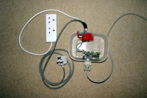
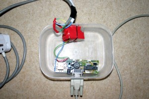
Additionally in order to make the design even safer (with respect to dealing with the 230V AC supply) I added a second relay. The reason is that if I had used the on-board relay full 230V AC would be arriving on the relay terminals on the board. Instead a second relay is driven using the relay that is on the board. As you can see in the images the on-board relay is orange in color whereas the second relay is separate to the board and has Red tape over it. So whenever the relay on the board is driven it provides supply to the external relay turning the second relay ON or OFF.
Step 9: Going Wireless!
The main idea is to make the interfacing between the computer and the micro-controller board wireless. It is important to know that there are quite a lot of very cheap different types of off-the-shelf wireless modules available. Many of these modules provide simple serial communication protocol the RS232 over a wireless protocol. For an example, such Bluetooth module can provide serial communication over Bluetooth protocol. Similarly modules providing Serial communication protocol over Wifi and RF are also available. Let’s take an example of Bluetooth protocol for making the home automation system wireless.
1) For the micro-controller board: You can get one of the Bluetooth modules with Serial interface and connect the RX, TX and GND pins to the micro-controller serial interface pins. You need to take care of the voltage levels while interfacing with the micro-controller or a micro-controller board, most of these wireless modules can work with 5 or 3.3V.
2) For a PC you could use a Bluetooth-USB dongle that emulates serial port over Bluetooth. This means when you connect the dongle to your PC, it will show up as a Serial/COM port. Then it is quite simple, you can use the same ‘C’ application and same speech recognition software as mentioned in this project to send command to the Bluetooth dongle via the emulated COM port thus making this home automation system wireless. Very simple.
I leave it upto you to find out various ways to control this home automation system with countless Bluetooth enabled devices.
Step 10: General List of Components
The following is a general list of components, just to give you an idea to what is required.
1 × Windows PC/Laptop with Internal/External Microphone
1 × Serial – RS232 cable
1 × Olimex PIC-MT, 28 pin PIC or similar micro-controller development board with onboard relay & serial port
Alternatively an Arduino board with a shield having 230V Relay.
1 × 12V DC power supply to power the micro-controller board
1 × Tazti or similar speech recognition software
1 × AC – 230 V power socket with cable (to interface with the relay)
1 × AC – 230 V power plug with cable (to interface with relay)

I would like to share with you how I managed to provide Bluetooth capability to my relatively old home cinema system.
Step 1: Requirements
1) One of the main requirements is not to have a rechargeable solution because it becomes annoying when you need to recharge frequently.
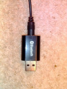
2) A cheap Bluetooth audio receiver with a male Universal Serial Bus (USB) port, a stereo (3.5mm female) audio output port and without a battery (as shown in the image). Such receivers are available for 2£-3£ on some of the popular e-commerce websites. If you buy one of those rechargeable one then you will have to keep recharging them.
3) I own a relatively older DVD 5.1 home-cinema music system. This system does not have wireless capability. So I have been thinking to provide it with some form of wireless capability for an example, Bluetooth.
It is important to note here that the system has and is required to have:
a) a female USB port (this interfaces with USB sticks and can play songs from it). This port is to be used to supply power to the receiver without this the receiver will have to be powered externally.
b) a 3.5 mm standard stereo audio input
4) A stereo (3.5 mm) male to male cable. Normally this is shipped with the receiver.
Step 2: Simple Setup
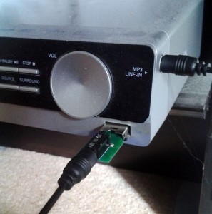
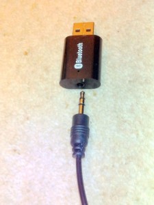
The main idea here is to supply the necessary power to the receiver from the system’s USB port and obtain the audio output from the receiver and provide it to the stereo input of the system.
The USB port of the system accepted USB-sticks and could play songs from it. This means the USB port (system) will try to access the data pins of any USB device plugged to the port. This can create a problem and also hang the system if the USB device is not a storage device such as USB-stick or pen-drive. This is because such older systems with USB capabilities could not access any other non-storage USB devices.
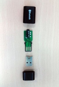
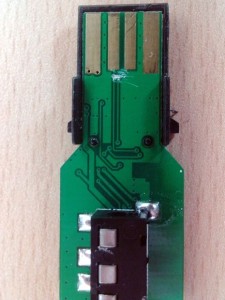
Also, I observed that my system froze when I plugged the receiver into its USB port. So I opened the USB Bluetooth audio receiver to check whether there were connections made to the Bluetooth chip from the data pins of the USB port on the Printed Circuit Board (PCB) of the receiver and I was right. So as shown in the images, I cut the middle two tracks which are the USB data signals, on the PCB of the receiver with a pen knife.
Step 3: How to connect various bits
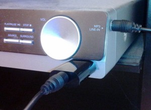
Now, plug in your Bluetooth audio receiver into the USB port of the system. So this will provide the necessary power supply to the receiver. Then plug in one end of the Stereo 3.5mm male to male cable into the output of the receiver and the other end into the input of your system. This is to pipe the audio from the output of the receiver into the input of your media player.
The system has now Bluetooth capability. You should be able to play songs directly from any Bluetooth enabled device such as your smartphone or a tablet to the media player system.
Step 4: Other Applications
Please note, this solution can be deployed to any such media system, for an example your car’s audio player and enjoy Bluetooth capability without the hassle of charging.
Also, if your system does not have a female USB port then you can supply the power to the receiver from an external USB power supply or buy a Bluetooth audio receiver that has rechargeable battery in it.